
Bottom pouring system

A pouring system and bottom-injection technology, used in casting molding equipment, molds, cores, etc., can solve the problems of easy fracture of ceramic cores, premature solidification of the selection end before crystal pulling, and insufficient slag filtration. Simple structure, improved grain orientation pass rate, and easy assembly

Active Publication Date: 2017-10-27
CHINA HANGFA SOUTH IND CO LTD
View PDF7 Cites 2 Cited by
  • Summary
  • Abstract
  • Description
  • Claims
  • Application Information

AI Technical Summary

Problems solved by technology

[0004] The invention provides a bottom pouring pouring system to solve the technical problems of easy fracture of the ceramic core, insufficient dregs filtering, and early solidification of the selected crystal end before crystal pulling when the existing top pouring pouring system is used for pouring

Method used


Image

  • Bottom pouring system
  • Bottom pouring system
  • Bottom pouring system

Examples


Embodiment Construction

[0028] The embodiments of the present invention will be described in detail below with reference to the accompanying drawings, but the present invention can be implemented in many different ways defined and covered by the claims.

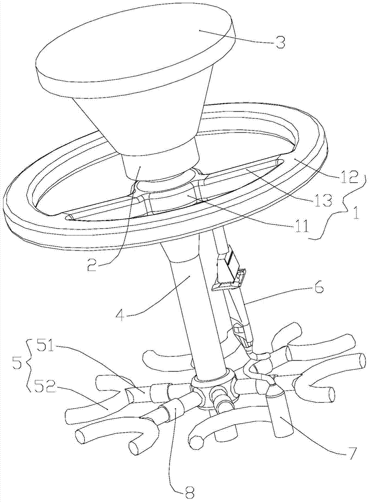
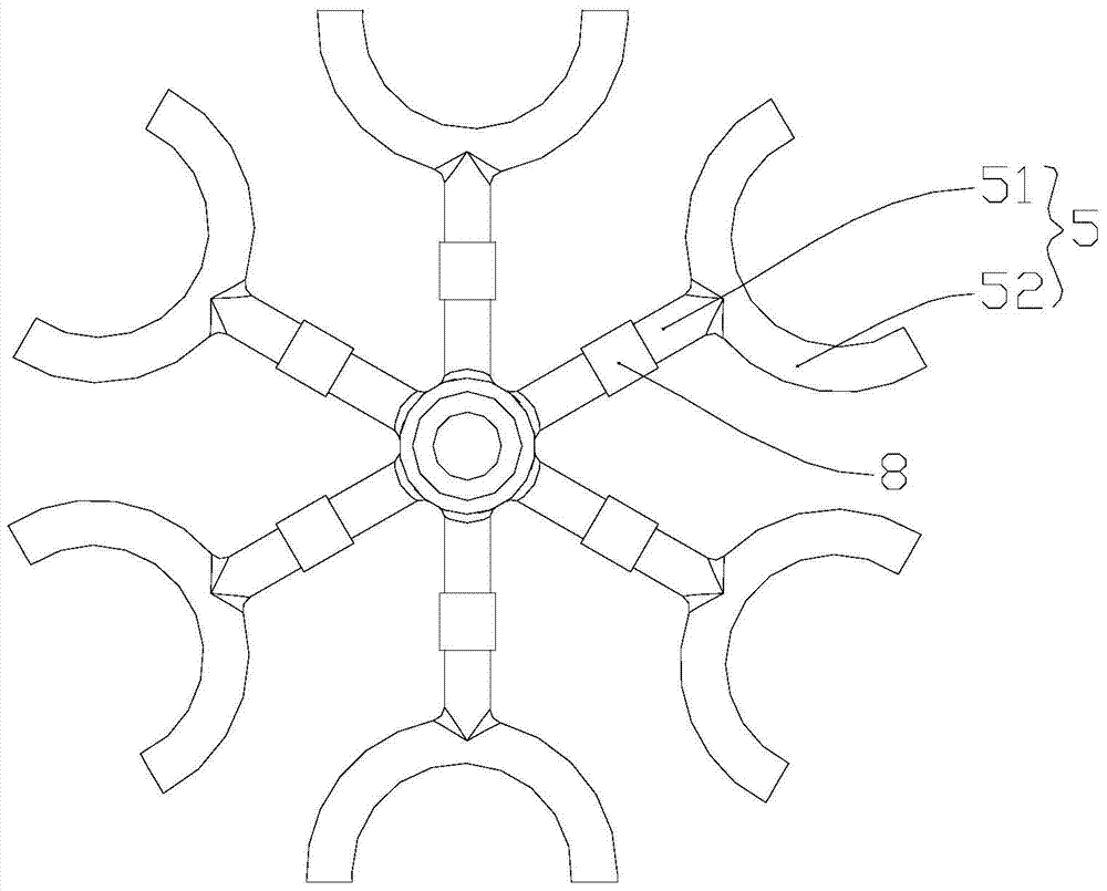
[0029] like image 3 As shown, the preferred embodiment of the present invention provides a bottom pouring gating system, comprising a disc runner 1, the disc runner 1 includes a disc main sprue 11 for the pouring liquid to pass through, and the disc main sprue 11 The upper end of the first filter screen 2 is connected with the first filter screen 2 for filtering the pouring liquid, and the upper end of the first filter screen 2 is connected with the sprue cup 3 for introducing the pouring liquid; the lower end of the disc main pouring pipe 11 is connected with a vertical center column Runner 4, the bottom end of the center column runner 4 is connected with the bottom pouring runner 5; the disc runner 1 is connected with the blade 6, and the bottom ...


PUM


Abstract

The invention discloses a bottom pouring type pouring system. The bottom pouring type pouring system comprises a disc pouring gate which comprises a main disc pouring pipe allowing pouring liquid to pass through, a first filtering net used for filtering the pouring liquid is connected to the upper end of the main disc pouring pipe, and a pouring cup used for leading in the pouring liquid is connected to the upper end of the first filtering net; a vertically-arranged middle column pouring gate is connected to the lower end of the main disc pouring pipe, and a bottom pouring gate is connected to the bottom end of the middle column pouring gate; and a blade is connected to the disc pouring gate, a spiral crystal selecting device for molding the blade into a single crystal blade is connected to the bottom end of the blade, and the bottom end of the spiral crystal selecting device is communicated with the bottom pouring gate so as to enable the pouring liquid to enter the spiral crystal selecting device from the bottom end of the spiral crystal selecting device. In the bottom pouring type pouring system, the effective length of the spiral crystal selecting device is effectively guaranteed, the crystal orientation acceptability of the single crystal blade is improved, mold filling is stable, impact of the high-temperature pouring liquid to a ceramic core of the blade is reduced, the bottom pouring type pouring system is simple in structure, and assembling of all components of a module is easy and convenient.

Description

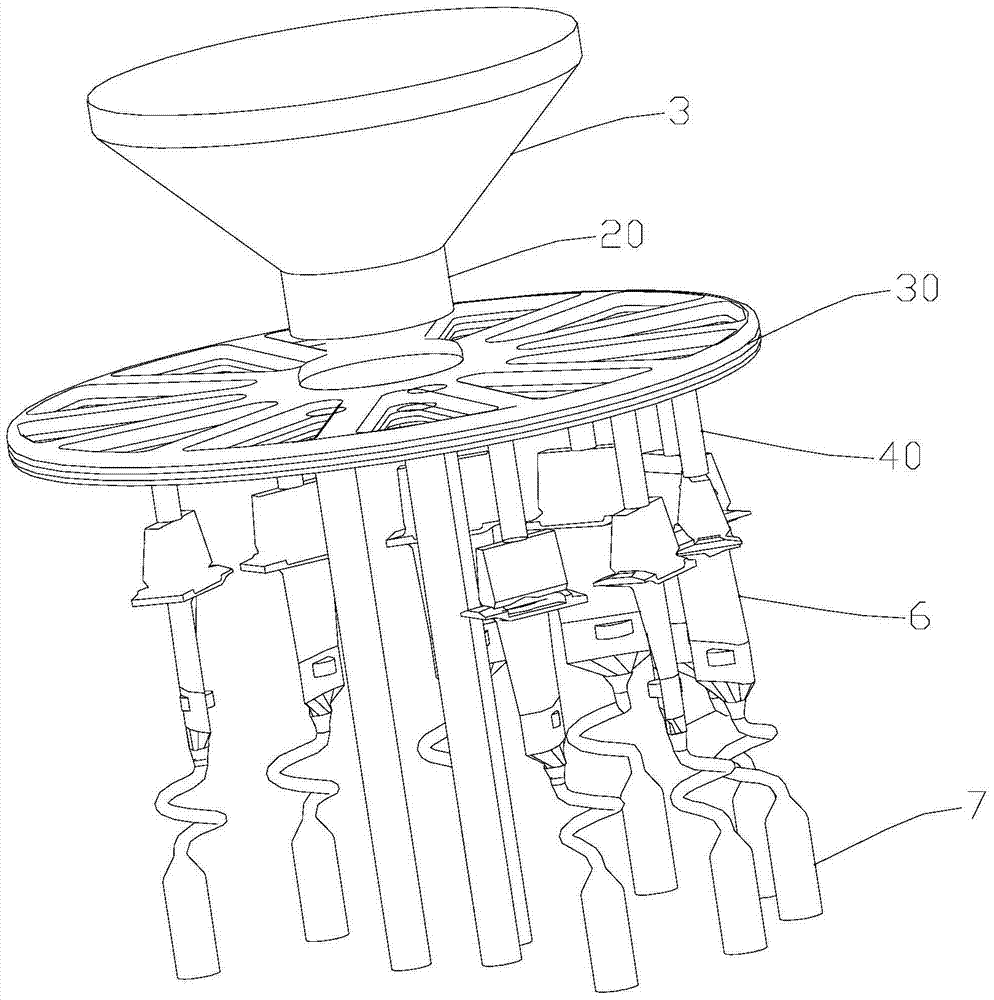
technical field [0001] The invention relates to the field of aero-engines, in particular to a bottom pouring pouring system. Background technique [0002] During the pouring process of single crystal directional blades, the pouring method of injecting molten steel from the top of the blade is generally adopted. The top injection pouring system of single crystal directional blades is shown in the attached figure figure 1 As shown, the flow direction of molten steel in this pouring method is: sprue cup 3-filter 20-blade top circular runner 30-blade top sprue 40-blade 6-spiral crystal selector 7. [0003] In the single-crystal directional blade top-injection pouring system, since the molten steel is directly impacted from the top of the blade, the impact force on the ceramic core of the blade 6 is very large, which may easily cause the ceramic core to break; secondly, due to the top-injection pouring There is only one layer of filter screen 20 in the system, which cannot compl...

Claims


Application Information

Patent Timeline
Patent Type & Authority Patents(China)
IPC IPC(8): B22C9/08
Inventor 李振锋王玉雷郝新雷四雄侯正乾闫彬梁亚飞
Owner CHINA HANGFA SOUTH IND CO LTD
Learn More