Electronic commutation control system and control method for variable-capacitance electrostatic motor

A technology of electronic commutation and variable capacitance, which is applied in the direction of electrostatic generator/motor, electrostatic motor, generator/motor, etc., can solve the problems of stator drive pulse out-of-step, long add-on time, motor out-of-step, etc., to achieve Reduce the starting time and solve the effect of motor out of step

Active Publication Date: 2016-01-27
TSINGHUA UNIV
View PDF4 Cites 2 Cited by
  • Summary
  • Abstract
  • Description
  • Claims
  • Application Information

AI Technical Summary

Problems solved by technology

The variable capacitance electrostatic motor is a synchronous motor, when the micro motor works at 10 -1 Under the vacuum condition of Pa or lower, the residual gas damping is very small, and the phase stability margin of the rotation control loop is extremely low, which may easily cause the motor to lose step and fail to work normally.
In addition, in the process of driving the micro-motor to rotate, the disturbance torque caused by temperature and air pressure changes, processing error and electrostatic bearing force coupling inside the motor will directly affect the synchronous rotation of the motor.
The traditional open-loop commutation control method does not require the current position information of the rotor, and the motor control scheme is simple, but in order to avoid the motor out of step during the acceleration process, it usually takes a long acceleration time; on the other hand, when the disturbance torque is large, It is easy to cause the rotor rotation and the stator drive pulse to be out of sync, and the motor cannot run stably for a long time

Method used


Image

  • Electronic commutation control system and control method for variable-capacitance electrostatic motor
  • Electronic commutation control system and control method for variable-capacitance electrostatic motor
  • Electronic commutation control system and control method for variable-capacitance electrostatic motor

Examples


Embodiment Construction

[0014] The electronic commutation control system and control method of the variable capacitance electrostatic motor provided by the present invention will be further described in detail below in conjunction with the accompanying drawings and specific embodiments.

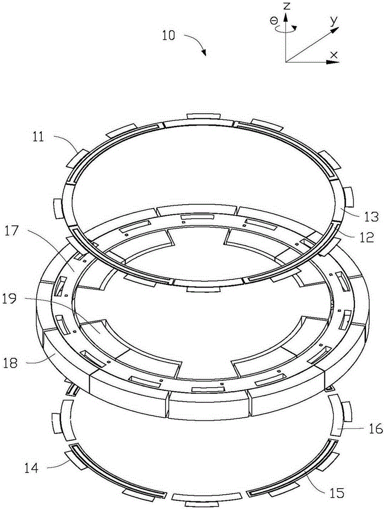
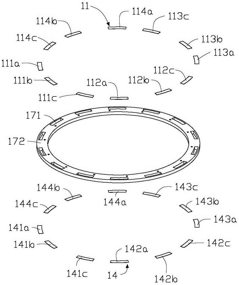
[0015] see figure 1 , The silicon micro-static levitation motor 10 includes a three-layer structure of top glass, middle layer of highly doped silicon, and bottom glass. There are upper stator 11 , axial suspension electrode 12 and common electrode 13 on the glass surface of the top layer. There are lower stator 14 , axial suspension electrode 15 and common electrode 16 on the bottom glass. There is a rotor 17 on the middle highly doped silicon layer, and in the radial direction of the rotor 17, there are suspended electrodes 18 with an outer diameter and suspended electrodes 19 with an inner diameter. The rotor 17 maintains a micron-scale gap with the upper stator 11, the lower stator 14, the axial suspension ele...


PUM


Abstract

The invention relates to an electronic commutation control system of a variable-capacitance electrostatic motor. The electronic commutation control system comprises a rotation speed / rotation angle detecting unit, a micro controller and an output amplifying unit. The invention also provides an electronic commutation control method of a variable-capacitance electrostatic motor. The method includes the following steps that: S1, driving voltage is applied, and a rotor starts rotating at a ti time point, and the rotation speed / rotation angle detecting unit is utilized to only provide one path of rotation speed signals of the rotor; S2, the micro controller is utilized to capture the rising edge of the rotation speed signals of the rotor, and a time point at this moment is recorded as ti+1, and a rotation speed signal cycle Ti can be expressed by the equation that Ti=t(i+1)-ti, wherein i is an integer, and a rotation speed coefficient ks is set to belongs to (0, 1], and ks*Ti / 3 is set to be pulse width required by driving voltage at a next cycle; S3, the output amplifying unit is utilized to output three-phase driving voltage signals; and S4, S2 and S3 are repeated, and therefore, high-speed synchronous rotation of the rotor can be realized.

Description

technical field [0001] The invention relates to an electronic commutation control system and a control method of a variable capacitance electrostatic motor. Background technique [0002] The silicon micro-static levitation motor is processed by the MEMS bulk silicon process, and is stably suspended in the geometric center of the vacuum electrode cavity by using the electrostatic support system, which can effectively avoid contact, friction and wear, and has the advantages of high working stability and long service life. And, when the motor speed works to 10 4 It can be used as a high-precision and high-resolution two-degree-of-freedom rate gyroscope when it is above rpm. The variable capacitance electrostatic motor is a synchronous motor, when the micro motor works at 10 -1 When the vacuum condition is Pa or lower, the residual gas damping is very small, and the phase stability margin of the rotation control loop is extremely low, which will easily cause the motor to lose ...

Claims


Application Information

Patent Timeline
IPC IPC(8): H02N1/00
CPCH02N1/002
Inventor 韩丰田孙搏谦李林林刘天一
Owner TSINGHUA UNIV
Why Eureka
Try Eureka