
Control device and method for converter smelting through CO2 and argon of rotary kiln

A converter smelting and control device technology, applied in the field of metallurgy and steel, can solve the problems of difficult to recover and discharge carbon dioxide, difficult to utilize waste heat, pollute environmental energy and other problems, and achieve the effects of easy control of decomposition temperature, reduction of production cost and high temperature

Inactive Publication Date: 2016-01-27
李正福
View PDF4 Cites 4 Cited by
  • Summary
  • Abstract
  • Description
  • Claims
  • Application Information

AI Technical Summary

Problems solved by technology

Because lime is mixed with fuel and burned together, the carbon dioxide produced by decomposition contains residual gas, and it is difficult to recycle the discharged carbon dioxide. Moreover, the high-temperature flue gas generated by combustion contains a lot of dust, so it is difficult to recycle, the cost is high, and the waste heat is difficult to use. At present, almost Directly discharged into the atmosphere, causing environmental pollution and energy waste, which does not meet the national requirements of circular economy and low-carbon emissions. Therefore, there is an urgent need for a pure carbon dioxide technology that fundamentally solves the separation, extraction, and low cost of calcined limestone.

Method used


Image

  • Control device and method for converter smelting through CO2 and argon of rotary kiln
  • Control device and method for converter smelting through CO2 and argon of rotary kiln

Examples


Embodiment Construction

[0038] The technical solutions of the present invention are described below through specific embodiments. On the premise that there is no conflict with the purpose of the present invention, the embodiments mentioned below and the technical features in the embodiments can be combined with each other.

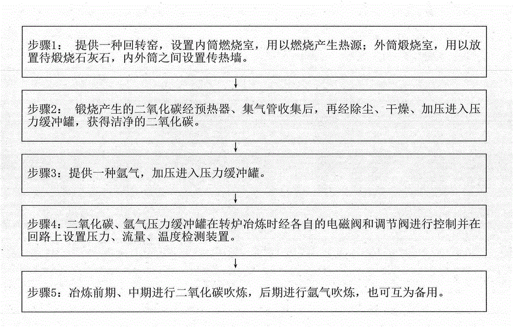
[0039] Such as figure 1 As shown, the technical solution adopted in the present invention is: the rotary kiln part includes a rotary kiln inner cylinder combustion chamber for combustion to generate heat; an outer cylinder calciner chamber for placing limestone to be calcined, and a heat transfer wall is arranged between the inner and outer cylinders. The carbon dioxide produced after calcining limestone is preheated by the preheater to the limestone, collected by the gas collecting pipe, and then dedusted, dried and pressurized into the pressure buffer tank to obtain clean carbon dioxide gas; the converter smelting part includes carbon dioxide gas, argon The compound smelting co...


PUM


Abstract

The invention provides a control device and method for converter smelting through CO2 and argon of a rotary kiln. The control device comprises a rotary kiln part and a converter smelting part. An inner cylinder combustion chamber used for performing combustion to generate a heat source and an outer cylinder calcining compartment used for containing to-be-calcined limestone are arranged in the rotary kiln. A heat transmission wall is arranged between an inner cylinder and an outer cylinder. After carbon dioxide generated through calcination is collected through a preheater and a gas collecting pipe, dust removing, drying and pressurizing are carried out on the carbon dioxide, then the carbon dioxide enters pressure buffering tanks, and the clean carbon dioxide is obtained. The converter smelting part comprises a composite carbon dioxide and argon blowing control system mainly composed of the carbon dioxide and argon pressure buffering tanks, pressure detecting devices, flow detecting devices, temperature detecting devices, electromagnetic valves, adjusting valves and the like. During smelting, the respective electromagnetic valves and the respective adjusting valves are used for performing controlling, carbon dioxide blowing is carried out in the earlier stage and the medium stage, argon blowing is carried out in the later stage, and the electromagnetic valves and the adjusting valves can complement one another. According to the control device and method, the steelmaking production cost is reduced, the carbon emission and greenhouse effect can be reduced, and the control device and method conform to circular economy.

Description

technical field [0001] The invention relates to the field of metallurgy and iron and steel, in particular to a smelting control device and method for compounding carbon dioxide gas produced by indirect calcined limestone and externally supplied argon in the metallurgical industry for steelmaking converters. Background technique [0002] The 2009 Copenhagen Climate Change Symposium brought the low-carbon economy into the global focus. The low-carbon economy is an economic development model based on low energy consumption, low pollution, and low emissions. It is a fundamental change to the current production mode that consumes a lot of fossil energy and emits a lot of carbon dioxide. In 2005, it decreased by 40-45%, and was incorporated into the medium and long-term planning of national economic and social development as a binding indicator. [0003] Carbon dioxide emissions in the steel production process account for about 16% of industrial carbon dioxide emissions, and the ...

Claims


Application Information

Patent Timeline
Patent Type & Authority Applications(China)
IPC IPC(8): C21C5/34C04B2/10C01B31/20C01B32/50
CPCY02P40/40
Inventor 李正福李宁燕
Owner 李正福
Learn More