
Evaporator for rose extraction

A technology of evaporators and rosettes, which is applied in the direction of distillation adjustment/control, distillation in boilers/distillates, and fat generation. It can solve problems such as waste of resources, low processing efficiency, and low work efficiency, and achieve improved work efficiency and automation. High degree, good evaporation effect

Inactive Publication Date: 2016-01-27
HUBEI SAATCNI EARTH AGRI IND DEV CO LTD
View PDF0 Cites 0 Cited by
  • Summary
  • Abstract
  • Description
  • Claims
  • Application Information

AI Technical Summary

Problems solved by technology

[0002] After enzymatic hydrolysis and aroma enhancement, rose raw materials need to be cyclically distilled in a vacuum environment below 80 degrees, so this process has extremely high requirements on the evaporator. The evaporator is mainly composed of a heating chamber and an evaporation chamber. The traditional evaporation Due to the structure of the device, the raw material needs to be heated for a long time to make the original material boil, and then complete the work of evaporation and screening. However, the heating process is long and requires a long time of energy supply. At the same time, the steam is rising. It is easy to condense and needs to be heated repeatedly. The processing efficiency is low, time-consuming and labor-intensive, and a lot of resources are wasted. In addition, the existing evaporator does not have a heat preservation device, which easily causes a temperature difference between the upper and lower sides during the evaporation process, which affects the distillation of roses; another On the one hand, the vacuum environment is very important for the distillation of roses. After the distillation is completed, it needs to be transported with a delivery tube, and the work efficiency is low.

Method used

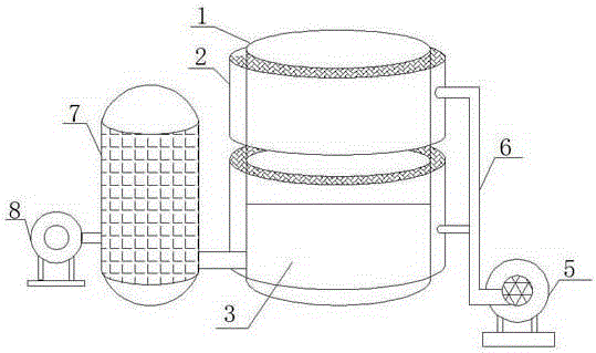

Image

  • Evaporator for rose extraction
  • Evaporator for rose extraction
  • Evaporator for rose extraction

Examples


Embodiment Construction

[0017] The preferred embodiments of the present invention will be described below in conjunction with the accompanying drawings. It should be understood that the preferred embodiments described here are only used to illustrate and explain the present invention, and are not intended to limit the present invention.

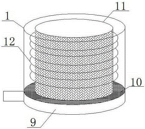
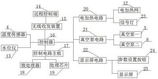
[0018] Such as Figure 1-3 As shown, an evaporator for extracting roses of the present invention includes a body 1, an inner container 11 is provided in the body 1, and an upper insulation layer 2 and a lower insulation layer 3 are arranged outside the body 1. The inner container 11 through the connecting pipeline 6 and the storage tank 7, the storage tank 7 is connected with the vacuum pump 2 through the connecting pipeline 6, and an electric heating network 12 is arranged between the inner tank 11 and the upper insulation layer 2 and the lower insulation layer 3, so that The bottom of the inner tank 11 is provided with a base 9, the top of the base 9 is provided w...


PUM


Abstract

The invention discloses an evaporator for rose extraction. The evaporator comprises a body, a liner is arranged in the body, an upper heat preservation layer and a lower heat preservation layer are arranged outside the body, the liner is connected with a storage tank through a connecting pipeline, and the storage tank is connected with a second vacuum pump through a connecting pipeline; an electric heating net is arranged between the liner and the upper heat preservation layer as well as between the liner and the lower heat preservation layer; a base is arranged at the bottom of the liner, a distilled water outlet is formed in the top of the base, and a distilling device is arranged in the base; the liner is connected with a first vacuum pump through a connecting pipeline, a temperature sensor and a water level instrument are arranged in the liner and are electrically connected with a controller, and the controller is connected with a remote control terminal through a wireless transmitting and receiving device and is electrically connected with an electric heating circuit. The evaporator for rose extraction is reasonable in design, good in evaporation effect and high in extraction rate.

Description

technical field [0001] The invention relates to the technical field of rose extraction equipment, in particular to an evaporator for rose extraction. Background technique [0002] After enzymatic hydrolysis and aroma enhancement, rose raw materials need to be cyclically distilled in a vacuum environment below 80 degrees, so this process has extremely high requirements on the evaporator. The evaporator is mainly composed of a heating chamber and an evaporation chamber. The traditional evaporation Due to the structure of the device, the raw material needs to be heated for a long time to make the original material boil, and then complete the work of evaporation and screening. However, the heating process is long and requires a long time of energy supply. At the same time, the steam is rising. It is easy to condense and needs to be heated repeatedly. The processing efficiency is low, time-consuming and labor-intensive, and a lot of resources are wasted. In addition, the existing...

Claims


Application Information

Patent Timeline
IPC IPC(8): B01D3/02B01D3/42C11B9/02
Inventor 陈驰宇
Owner HUBEI SAATCNI EARTH AGRI IND DEV CO LTD
Learn More