Eureka AIR delivers breakthrough ideas for toughest innovation challenges, trusted by R&D personnel around the world.

Spray type flue gas waste heat recycling device

A flue gas waste heat recovery device technology, applied in the direction of climate sustainability, greenhouse gas reduction, lighting and heating equipment, etc., can solve the problems of low proportion of flue gas latent heat recovery, high requirements for equipment anti-corrosion, and measures for flue gas purification , to achieve the effect of convenient operation and simple structure

Active Publication Date: 2016-01-20
BEIJING UNIV OF CIVIL ENG & ARCHITECTURE
View PDF8 Cites 9 Cited by
  • Summary
  • Abstract
  • Description
  • Claims
  • Application Information

AI Technical Summary

Problems solved by technology

[0006] The technical problem to be solved by the present invention is that the existing partition-type flue gas waste heat recovery equipment has partition thermal resistance, the recovery ratio of latent heat in the flue gas is relatively low, and the requirements for equipment anti-corrosion are high; the direct contact flue gas waste heat recovery equipment has no Questions about taking measures for flue gas purification

Method used


Image

  • Spray type flue gas waste heat recycling device
  • Spray type flue gas waste heat recycling device

Examples


Embodiment 1

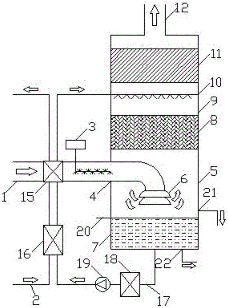
[0027] Such as figure 1 As shown, the spray type flue gas waste heat recovery device provided by the embodiment of the present invention includes a flue gas waste heat deep recovery unit and a flue gas purification unit. The flue gas waste heat deep recovery unit includes a main tower body 5, a first heat exchange 15 and the second heat exchanger 16, the water source is connected to the second heat exchanger 16 through the water inlet pipe 2, the main tower body 5 includes a condensation water collection section 7 and a spray heat exchange section 9, and the flue gas passes through the flue gas The gas pipeline 1 enters the spray heat exchange section 9 to recover the latent heat of the flue gas, and the solution is stored in the condensed water collection section 7 after heat exchange. The first heat exchanger 15 is arranged in the flue gas pipeline 1 for recovering the sensible heat of the flue gas. The condensed water collection section 7 is connected to the second heat ex...

Embodiment 2

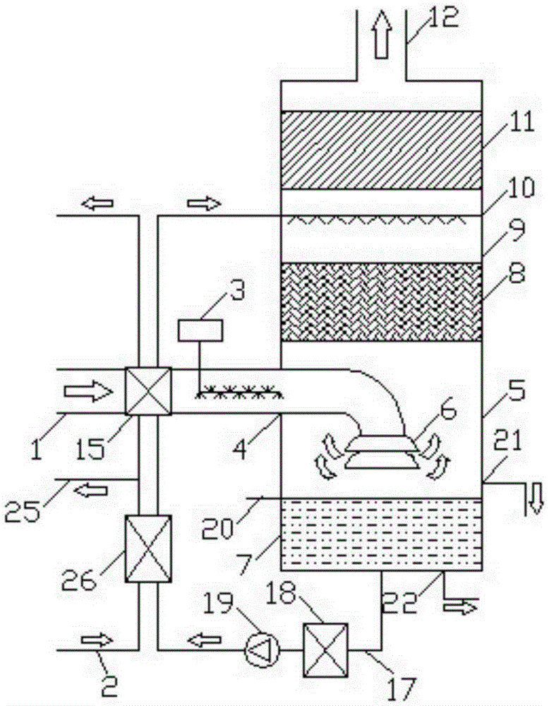
[0038] Since the heating efficiency of the second heat exchanger 16 is not as high as that of the electric heat pump unit 26, the temperature of the hot return water in the water inlet pipe 2 is 40°C. After being heated to 50°C by the second heat exchanger 16, it cannot reach the domestic heat. The supply temperature of the water. In this embodiment, the second heat exchanger 16 is replaced by an electric heat pump unit 26. The flue gas waste heat depth recovery unit includes the main tower body 5, the first heat exchanger 15 and the electric heat pump unit 26. The water source passes through the water inlet pipe 2 respectively Connected with the electric heat pump unit 26 and the first heat exchanger 15, the main tower body 5 includes a condensate collection section 7 and a spray heat exchange section 9, and the flue gas enters the spray heat exchange section through the flue gas pipeline 1 Section 9, the flue gas purification unit includes an oxidation device 3 communicated ...


PUM


Abstract

The invention relates to the technical field of flue gas recycling and discloses a spray type flue gas waste heat recycling device. The spray type flue gas waste heat recycling device comprises a flue gas waste heat deep-recycling unit and a flue gas purifying unit. The flue gas waste heat deep-recycling unit comprises a main tower body, a first heat exchanger and a second heat exchanger. A water source is connected with the second heat exchanger and the first heat exchanger through water inflow pipes. The main tower body comprises a condensation water collection segment and a spray heat exchange segment. Fuel gas enters the spray heat exchange segment through a fuel gas pipe. The first heat exchanger is arranged in the fuel gas pipe. The condensation water collection segment is connected with the second heat exchanger through a water outflow pipe. The fuel gas purifying unit comprises an oxidization device communicated with the fuel gas pipe. According to the spray type fuel gas waste heat recycling device, the fuel gas waste heat deep-recycling unit and the fuel gas purifying unit are arranged so that fuel gas waste heat can be recycled in a graded manner and pollutants in fuel gas can be purified, and the fuel gas waste heat deep-recycling function and the fuel gas purifying function are integrated in a coordinative manner.

Description

technical field [0001] The invention relates to the technical field of flue gas recovery, in particular to a spray type flue gas waste heat recovery device, in particular to a spray type flue gas waste heat recovery device capable of deeply recovering waste heat and purifying flue gas at the same time. Background technique [0002] At present, the exhaust gas temperature of traditional natural gas boilers operating in China is generally 150-250 °C. After combustion, the flue gas will generate water vapor with a volume share of about 20%, theoretically 1Nm 3 Natural gas combustion can produce 1.5Kg water vapor. The latent heat of vaporization released by the complete condensation of 1Kg of water vapor at 20°C is 2453KJ. Thus, 1Nm 3 The water vapor generated by the combustion of natural gas will contain about 3.6MJ of heat. The recovery of physical sensible heat and latent heat of vaporization in the flue gas can provide an energy utilization rate of more than 10%, which h...

Claims


Application Information

Patent Timeline
Patent Type & Authority Applications(China)
IPC IPC(8): F23J15/04F23J15/06B01D53/75B01D53/56
CPCY02E20/30
Inventor 张群力曹明凯张秋月
Owner BEIJING UNIV OF CIVIL ENG & ARCHITECTURE
Why Eureka
Eureka Blog
Learn More