
High-reliability installation method for high-voltage welding spots

A high-pressure welding and high-spot technology, which is applied in welding equipment, metal processing, metal processing equipment, etc., can solve the problems of satellite power supply and distribution subsystem failure, unsatisfactory long-term use, low-pressure discharge solder joints, etc., to prevent The effect of low pressure discharge phenomenon, round surface and reliable electrical connection

Active Publication Date: 2016-01-20
BEIJING SATELLITE MFG FACTORY
View PDF3 Cites 16 Cited by
  • Summary
  • Abstract
  • Description
  • Claims
  • Application Information

AI Technical Summary

Problems solved by technology

The shape of the solder joints will have different effects on the low-pressure discharge of the high-voltage solder joints. Conventional welding methods can easily lead to low-pressure discharges (solder joints tend to have sharp edges, etc.)
If the suppression measures for low-pressure discharge are not perfect, it may induce secondary arc discharge, which will lead to short circuit of power supply and cause failure of satellite power supply and distribution subsystem
[0003] For the forming, tinning, installation, welding, cleaning and inspection technology of high-voltage solder joints of such aerospace electronic products, if the existing assembly method is still used, it will not be able to meet the requirements of long-term use in harsh environments

Method used


Image

  • High-reliability installation method for high-voltage welding spots
  • High-reliability installation method for high-voltage welding spots
  • High-reliability installation method for high-voltage welding spots

Examples


Embodiment 1

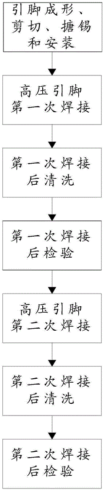
[0049] Step (1), forming and cutting the plug-in resistor pins, the length of the pins protruding from the soldering surface of the printed board is 0.5mm; tinning the cut pins, and tinning the plug-in resistors Resistor pins mounted into soldered through-holes on the printed board;

[0050] Step (2), first solder the plug-in resistor pins installed on the printed board:

[0051] Use a smart electric soldering iron to solder the pins for the first time, and the temperature of the soldering iron tip is 320°C. Welding time is 3s. When soldering, use one side (welding surface) welding method, that is, the solder flows from the welding surface to the component surface; after the first welding, the qualified plug-in pins and printed board solder joints refer to figure 2 shown;

[0052] For the first cleaning of the solder joints after the first soldering, manual cleaning is used, that is, the solder joints after the first soldering are repeatedly scrubbed with dust-free paper d...


PUM


Abstract

The invention discloses a high-reliability installation method for high-voltage welding spots. The high-reliability installation method is suitable for welding spots which are formed through welding of pins of 100-500 V plug-in mounting resistors, capacitors, diodes, connectors, TO package MOS tubes and other plug-in mounting devices and through hole bonding pads on printed boards, and welding spots which are formed through welding of wires and through hole pads on printed boards. According to the high-reliability installation method, before installation, forming and shearing of through hole element pins or wires are conducted, the length of the part, extending out from a welding face of a printed board, of a pin is optimally controlled, forming of a high-voltage welding spot can be better facilitated, and reliability of the welding spot is further improved; meanwhile, a high-voltage welding spot is formed through secondary welding, the surface of the welding spot formed through secondary welding is rounder, more smooth and free of pulling points, and the low-air-pressure discharging phenomenon can be easily prevented; and in addition, checking is conducted after two times of welding, it is ensured that the installed welding spots can resist low-air-pressure discharging, hot vacuum, vibration, impacts and other severe environment conditions, and installation reliability is ensured.

Description

technical field [0001] The invention relates to the field of electronic assembly, in particular to a highly reliable assembly method for high-voltage solder joints. Background technique [0002] Aerospace electronic products need to withstand the influence of harsh environmental conditions such as low-pressure discharge, thermal vacuum, vibration, and shock during operation. In order to improve the efficiency of the entire satellite power supply and distribution and solve the problem of low-voltage and high-current power supply in the power distribution system, some satellite platforms in my country have selected a 100V bus voltage system. The bus voltage of the platform reaches 100V, and the pin voltage of many components on the internal printed board of the single machine reaches 100V, and even the partial voltage reaches 170V, but the assembly of the solder joints is carried out according to the conventional process. The shape of the solder joints will have different eff...

Claims


Application Information

Patent Timeline
Patent Type & Authority Applications(China)
IPC IPC(8): B23K1/00B23K1/20
CPCB23K1/00B23K1/20B23K1/206B23K2101/36
Inventor 隋淞印高伟娜张晓超陈雅容
Owner BEIJING SATELLITE MFG FACTORY
Learn More