
Generation method of super-resolution optics pipeline

A super-resolution and optical technology, applied in the field of generation of super-resolution optical pipelines, can solve the problems of impracticability, small resolution, inconvenient use, etc., and achieve the effect of good intensity matching

Inactive Publication Date: 2016-01-13
UNIV OF SHANGHAI FOR SCI & TECH
View PDF6 Cites 8 Cited by
  • Summary
  • Abstract
  • Description
  • Claims
  • Application Information

AI Technical Summary

Problems solved by technology

This method of generating and suppressing light spots has many advantages, but there are still some essential deficiencies: 1) The focused light spots under 0 / π phase plate modulation with tangentially polarized light cannot be small enough to achieve smaller resolution; 2) The numerical aperture (NA) of the microscopic objective lens used for focusing is required to be 1 to 1.4, that is, the generated focused spot exists in the medium oil, which brings inconvenience to its use; 3) Because the NA is too high, the resulting focused spot axis The length is too short, which has great limitations for the realization of three-dimensional imaging

Method used


Image

  • Generation method of super-resolution optics pipeline
  • Generation method of super-resolution optics pipeline
  • Generation method of super-resolution optics pipeline

Examples


Embodiment Construction

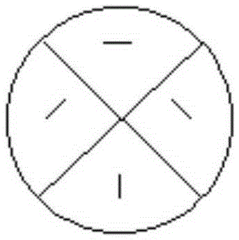
[0018] like figure 1 It is a schematic diagram of a device for producing a super-resolution optical pipeline. The optical axis direction is along the Z-axis direction. The laser 1 emits a laser beam that is polarized into linear polarization. The polarization direction is along the X-axis direction. After being collimated and expanded by the collimator beam expander 2, it is vertical Irradiated on the polarization converter 3, the polarization converter 3 is four half-wave plates glued together, and the direction of its slow axis is as follows: figure 2 As shown by the middle and short black lines, after the four pieces are glued together, each slow axis is within a quarter of the 3rd division of the polarization converter, and the slow axis of one piece is parallel to the optical axis. This parallel slow axis shall prevail, and the other slow axes Take the optical axis as the center and turn 45 degrees clockwise in sequence. After the polarization conversion modulation of t...


PUM


Abstract

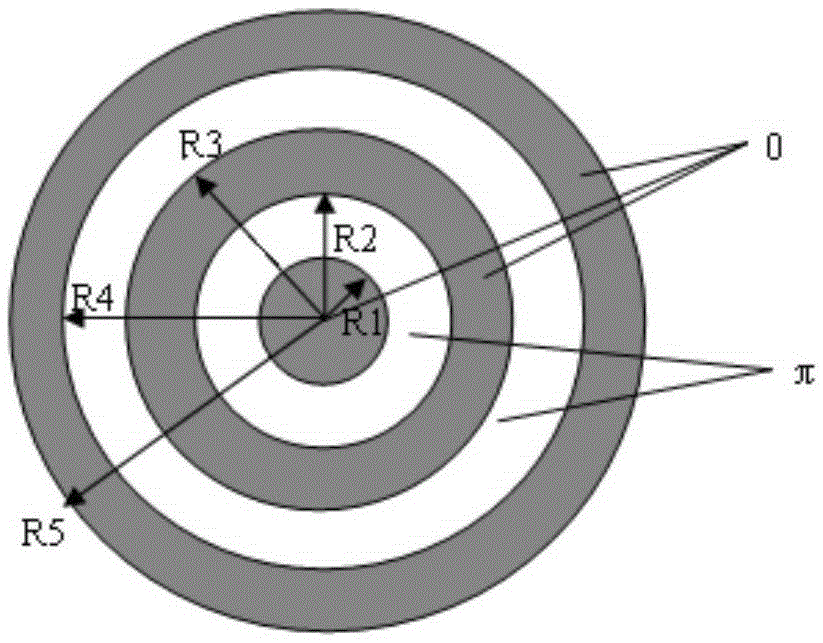
The present invention relates to a generation method of a super-resolution optics pipeline. The generation method of the super-resolution optics pipeline comprises: a laser emits a laser beam of linear polarization, and the laser beam is vertically irradiated to a polarization converter or a vortex phase plate along a direction of an optical axis after collimation and beam expanding through a collimation and beam expander so as to convert to an angular polarized light or a vortex light; a binary optics device is designed, five annular grooves with 0 / [Pi] alternation are engraved on a glass substrate, so that the phase of a light beam having a sizing ring belt which is zero is invariant and the phase delay of a light beam having a sizing ring belt which is a [Pi] is [Pi] after the angular polarized light or the vortex light vertically irradiate into the binary optics device; the angular polarized light or the vortex light are focused by passing through a microobjective with high numerical aperture after the modulation of the binary optics device, the destructive interference of the modulated light beams is performed at the focus, and a super-resolution optics pipeline is obtained. On the basis of the phase adjustment of the binary optics device provided by the invention, and a super-resolution optics pipeline with dark focused faculas at the focus of the microobjective and is taken as a de-excitation light source, so that the three-dimensional super-resolution imaging is realized.

Description

technical field [0001] The invention relates to an optical microscopy technique, in particular to a method for generating a super-resolution optical pipeline. Background technique [0002] For a long time, the Abbe diffraction limit has been considered as an insurmountable limit for optical microscopes, which limits the application of optical microscopes in observing microscopic and fine structures. Until the German scientist Stephen Hull invented the stimulated emission depletion (STED) microscope, which broke this limit and achieved far-field super-resolution, which was a milestone in biomedical research. The principle of the STED microscope is that the excitation light makes the fluorescent particles in the ground state transition to the excited state, and then the sample is irradiated with a circular de-exciting light source, causing the stimulated emission of the fluorescent substance, which consumes the number of particles at the energy level that can emit fluorescence...

Claims


Application Information

Patent Timeline
Patent Type & Authority Applications(China)
IPC IPC(8): G02B27/58G02B27/48
CPCG02B27/58G02B27/48
Inventor 王海凤姜利平朱厚飞刘玲玲
Owner UNIV OF SHANGHAI FOR SCI & TECH
Learn More