
Over excitation protection circuit of solid state power amplifier and implementation method thereof

A solid-state power and protection circuit technology, applied in the layout of amplifier protection circuits, improving amplifiers to reduce temperature/power supply voltage changes, etc., can solve the problems of noise factor deterioration limiter, can not solve the temperature characteristics of the power amplifier itself, to prevent low temperature Overdrive problem, effect of good linearity

Active Publication Date: 2016-01-06
SOUTHWEST CHINA RES INST OF ELECTRONICS EQUIP
View PDF5 Cites 8 Cited by
  • Summary
  • Abstract
  • Description
  • Claims
  • Application Information

AI Technical Summary

Problems solved by technology

[0006] Aiming at the technical problems that the use of limiter in the over-excitation protection circuit in the prior art leads to the deterioration of indicators such as harmonics, third-order intermodulation, and noise figure of the transmission system, and the limiter cannot solve the technical problems of over-excitation caused by the temperature characteristics of the power amplifier itself , the invention discloses an over-excitation protection circuit for a solid-state power amplifier

Method used


Image

  • Over excitation protection circuit of solid state power amplifier and implementation method thereof
  • Over excitation protection circuit of solid state power amplifier and implementation method thereof

Examples


Embodiment Construction

[0019] The specific implementation manners of the present invention will be described in detail below in conjunction with the accompanying drawings.

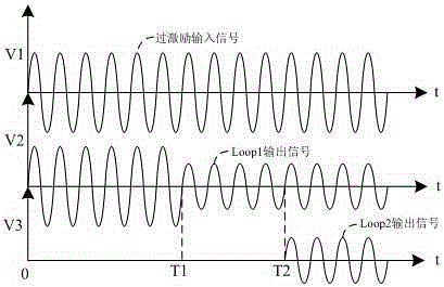
[0020] The invention discloses an over-excitation protection circuit of a solid-state power amplifier, which specifically includes an automatic level control loop and a switch control loop. Open the RF switch to prevent the over-excitation signal before starting the control from entering the RF amplification link. The automatic level control loop includes a coupler 11, a detection amplifier circuit 12, a first comparator 13, a first threshold circuit 22 and a voltage control circuit. Attenuator 14, the input end of the voltage-controlled attenuator 14 is connected to the input of the main signal, and the output end is connected to the input end of the coupler 11, a part of the signal of the coupler 11 is output to the detection amplifier circuit 12, and a part of the signal is output to the switch control loop The radio frequenc...


PUM


Abstract

The invention relates to the technical field of solid state power amplifiers, and discloses an over excitation protection circuit of a solid state power amplifier. The over excitation protection circuit specifically comprises an automatic level control loop and a switch control loop. A threshold of the automatic level control loop is set to stabilize over excitation input power at a certain rated power level; and a time delay or a threshold of the switch control loop is set to turn on a radio frequency switch after the automatic level control loop starts to control, so as to prevent an over excitation signal prior to control from entering a radio frequency amplification link. By means of the cooperative use of the two circuits, when an over excitation signal is input, subsequent equipment is protected, and meanwhile, the amplitude of the input over excitation signal is controlled instead of simply preventing over excitation by the on-off of a time delay switch used in the prior art. A universal over excitation protection device limiter is not used in the over excitation protection circuit disclosed by the invention, thereby avoiding the deterioration of such indexes as transmission system harmonics, third-order cross modulation, noise coefficient and the like. The invention further discloses an implementation method of over excitation protection circuit of the solid state power amplifier.

Description

technical field [0001] The invention relates to the technical field of solid-state power amplifiers, in particular to an over-excitation protection circuit and an implementation method of a solid-state power amplifier. On the premise of not deteriorating the linearity, the over-excitation caused by too large input signal and the problem caused by its own temperature characteristics are solved at the same time. over motivated. Background technique [0002] The output power of the solid-state power amplifier gradually saturates as the input power increases. If the input power continues to increase (over-excitation), the linearity indicators such as harmonics, third-order intermodulation, and noise figure of the system will quickly deteriorate. At the same time, the solid-state Power devices such as gallium arsenide and gallium nitride microwave power tubes may cause burnout. [0003] During the use of solid-state power amplifiers, overdrive mainly comes from two aspects. One...

Claims


Application Information

Patent Timeline
Patent Type & Authority Applications(China)
IPC IPC(8): H03F1/30H03F1/52
Inventor 敬小东罗嘉邱钢杨光
Owner SOUTHWEST CHINA RES INST OF ELECTRONICS EQUIP
Learn More