Multi-jet friction yarn-forming apparatus of electrostatic spinning nano fiber and manufacturing method thereof
A technology of nanofiber and spinning device, which is applied in fiber processing, yarn, textile and paper making, etc. It can solve the problems of low output, small fineness, unstable spinning process, etc., achieve high output, increase added value, and prepare The effect of simple process
- Summary
- Abstract
- Description
- Claims
- Application Information
AI Technical Summary
Problems solved by technology
Method used
Image

Examples
Embodiment 1
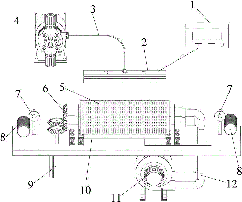
[0041] Refer to attached figure 1 , attached figure 2 , attached image 3 , attached Figure 4 And attached Figure 5 , a multi-strand air-jet friction yarn forming device for electrospinning nanofibers, which includes a high-voltage generator 1, a spinning device 2, a liquid supply device 4, a friction roller 5, a metal rod 10, a yarn guide 7, and a winding device 8 , motor 9 and turbo blower 11.
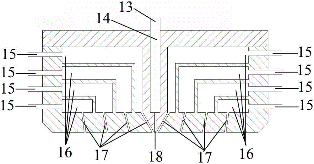
[0042] The spinning device 2 is connected with the liquid supply device 4 through the infusion tube 3 . Two friction rollers 5 arranged in parallel are arranged directly under the spinning device, one end of the two friction rollers 5 is connected with the motor 9 through the gear 6 , and the other end is connected with the vortex fan 11 through the suction pipe 12 . Both ends of the friction roller 5 are respectively provided with a yarn guide 7 and a winding device 8 , and a metal rod 10 is installed under the friction roller 5 . The positive and negative poles of the high...
Embodiment 2
[0060] Refer to attached figure 1 , attached figure 2 , attached image 3 , attached Figure 4 And attached Figure 5 , a multi-strand air-jet friction yarn forming device for electrospinning nanofibers, which includes a high-voltage generator 1, a spinning device 2, a liquid supply device 4, a friction roller 5, a metal rod 10, a yarn guide 7, and a winding device 8 , motor 9 and turbo blower 11.
[0061] The spinning device 2 is connected with the liquid supply device 4 through the infusion tube 3 . Two friction rollers 5 arranged in parallel are arranged directly under the spinning device, one end of the two friction rollers 5 is connected with the motor 9 through the gear 6 , and the other end is connected with the vortex fan 11 through the suction pipe 12 . Both ends of the friction roller 5 are respectively provided with a yarn guide 7 and a winding device 8 , and a metal rod 10 is installed under the friction roller 5 . The positive and negative poles of the high...
Embodiment 3
[0079] Refer to attached figure 1 , attached figure 2 , attached image 3 , attached Figure 4 And attached Figure 6 , a multi-strand air-jet friction yarn forming device for electrospinning nanofibers, which includes a high-voltage generator 1, a spinning device 2, a liquid supply device 4, a friction roller 5, a metal rod 10, a yarn guide 7, and a winding device 8 , motor 9 and turbo blower 11.
[0080]The spinning device 2 is connected with the liquid supply device 4 through the infusion tube 3 . Two friction rollers 5 arranged in parallel are arranged directly under the spinning device, one end of the two friction rollers 5 is connected with the motor 9 through the gear 6 , and the other end is connected with the vortex fan 11 through the suction pipe 12 . Both ends of the friction roller 5 are respectively provided with a yarn guide 7 and a winding device 8 , and a metal rod 10 is installed under the friction roller 5 . The positive and negative poles of the high ...
PUM
| Property | Measurement | Unit |
|---|---|---|
| Surface aperture | aaaaa | aaaaa |
| Diameter | aaaaa | aaaaa |
| Diameter | aaaaa | aaaaa |
Abstract
Description
Claims
Application Information
 - R&D
- Intellectual Property
- Life Sciences
- Materials
- Tech Scout
- Unparalleled Data Quality
- Higher Quality Content
- 60% Fewer Hallucinations
Browse by: Latest US Patents, China's latest patents, Technical Efficacy Thesaurus, Application Domain, Technology Topic, Popular Technical Reports.
© 2025 PatSnap. All rights reserved.Legal|Privacy policy|Modern Slavery Act Transparency Statement|Sitemap|About US| Contact US: help@patsnap.com