
Two-stage throttling complete cooling carbon dioxide refrigeration/ heat pump comprehensive experimental bench

A carbon dioxide and two-stage throttling technology, which is applied in the direction of heating and cooling combination, heat pump, refrigerator, etc., can solve the problems of low utilization rate of equipment, large laboratory area occupation, single function, etc.

Inactive Publication Date: 2015-12-30
TIANJIN UNIV OF COMMERCE
View PDF5 Cites 2 Cited by
  • Summary
  • Abstract
  • Description
  • Claims
  • Application Information

AI Technical Summary

Problems solved by technology

[0002] At present, most of the two-stage transcritical carbon dioxide experimental systems used in colleges and universities are simple heat pump systems, which have relatively single functions and low equipment utilization, which has caused a huge waste of resources invisibly; at the same time, scattered and single-function The test bench will occupy a large laboratory area; colleges and universities urgently need to integrate heat pump systems with single functions to reduce the floor area, improve the utilization rate of equipment, reduce the waste of the school in experiments, and improve the comprehensiveness of the school's experimental equipment. utilization rate

Method used


Image

  • Two-stage throttling complete cooling carbon dioxide refrigeration/ heat pump comprehensive experimental bench
  • Two-stage throttling complete cooling carbon dioxide refrigeration/ heat pump comprehensive experimental bench
  • Two-stage throttling complete cooling carbon dioxide refrigeration/ heat pump comprehensive experimental bench

Examples


Embodiment Construction

[0038] The present invention will be further described in detail below in combination with specific embodiments.

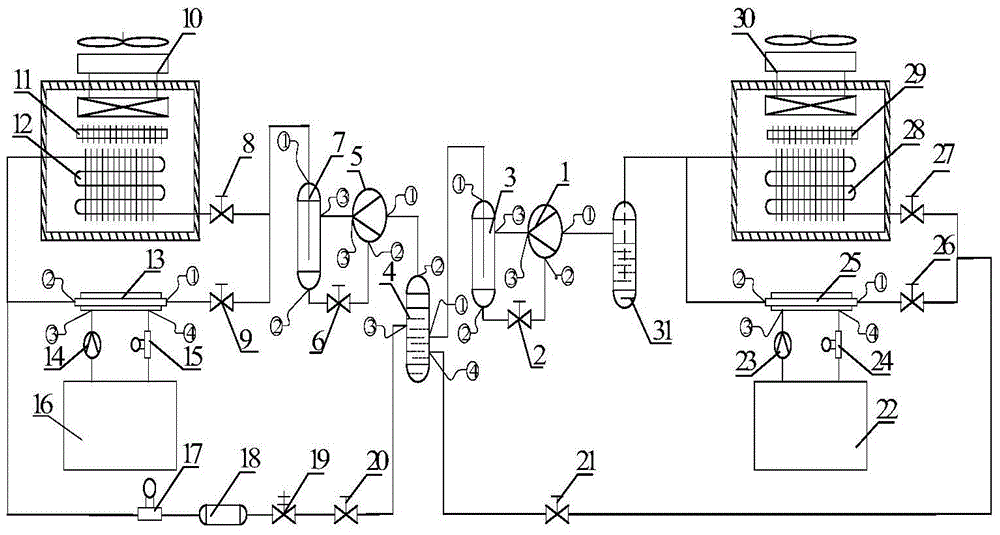
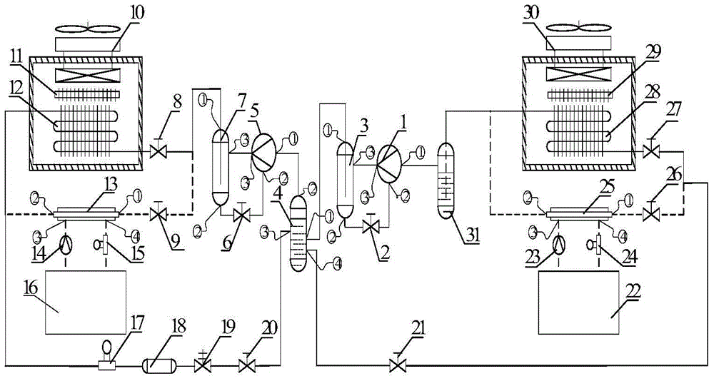
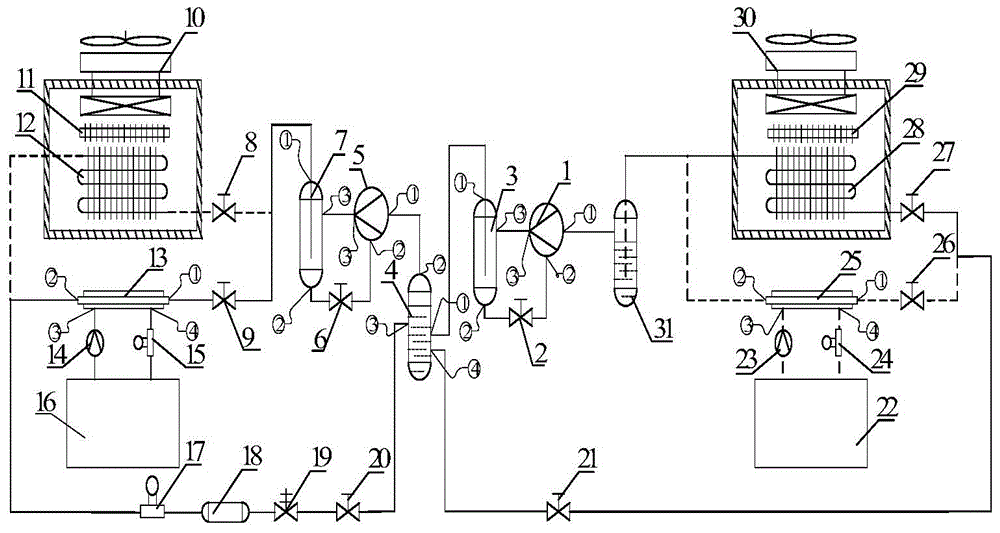
[0039] like figure 1 As shown, the present invention includes a carbon dioxide low pressure compressor 1, a valve one 2, a carbon dioxide oil separator one 3, a carbon dioxide gas-liquid separator one 4, a carbon dioxide high pressure compressor 5, a valve two 6, a carbon dioxide oil separator two 7, and a refrigerant cut-off Valve group, single air conditioner-10, electric heater-11, carbon dioxide finned tube heat exchanger-12, carbon dioxide shell-and-tube heat exchanger-13, water pump-14, flow meter-15, first heat preservation water tank 16 , flow meter 2 17, dry filter 18, solenoid valve 19, throttle valve 1 20, throttle valve 2 21, second heat preservation water tank 22, water pump 2 23, flow meter 3 24, carbon dioxide shell-and-tube heat exchanger 2 25. Carbon dioxide finned tube heat exchanger 2 28, electric heater 2 29, single air conditioner 2 30, carbo...


PUM


Abstract

The invention discloses a two-stage throttling complete cooling carbon dioxide refrigeration / heat pump comprehensive experimental bench. The experimental bench is constituted by a water system and a refrigerant system and comprises a carbon dioxide low pressure compressor, a first carbon dioxide oil separator, a first carbon dioxide gas-liquid separator, a second carbon dioxide gas-liquid separator, a carbon dioxide high pressure compressor, a second carbon dioxide oil separator, a refrigerant stop valve group, a first carbon dioxide shell-and-tube heat exchanger, a second carbon dioxide shell-and-tube heat exchanger, a first carbon dioxide finned tube heat exchanger, a second carbon dioxide finned tube heat exchanger, a first electric heater, a second electric heater, a first single type air conditioner, a second single type air conditioner, a first water pump, a second water pump, a first thermal insulation water tank, a second thermal insulation water tank, a flowmeter group, a drying and filtering device and the like. According to the comprehensive experimental bench, by operating on-off states of corresponding refrigerant stop valves, a two-stage trans-critical carbon dioxide air-cooling refrigeration system, an air source heat pump, a water-cooling refrigeration system, an air source condensation heat recovery system, an air-cooling water chilling unit system, a water source heat pump, a water-cooling water chilling unit system and a water source condensation heat recovery system of two stage throttling and completely cooled in the middle can be simulated.

Description

technical field [0001] The invention relates to a heat pump system, in particular to a two-stage throttling complete cooling carbon dioxide refrigeration / heat pump comprehensive experiment platform. Background technique [0002] At present, most of the two-stage transcritical carbon dioxide experimental systems used in colleges and universities are simple heat pump systems, which have relatively single functions and low equipment utilization, which has caused a huge waste of resources invisibly; at the same time, scattered and single-function The test bench will occupy a large laboratory area; colleges and universities urgently need to integrate heat pump systems with single functions to reduce the floor area, improve the utilization rate of equipment, reduce the waste of the school in experiments, and improve the comprehensiveness of the school's experimental equipment. utilization rate. Contents of the invention [0003] Aiming at the above-mentioned prior art, the pres...

Claims


Application Information

Patent Timeline
Patent Type & Authority Applications(China)
IPC IPC(8): F25B29/00F25B30/06F25B41/04F25B41/20
Inventor 孙志利臧润清刘圣春郭江河
Owner TIANJIN UNIV OF COMMERCE
Learn More