
Water desalination process and apparatus

a technology of water desalination process and water desalination apparatus, which is applied in the direction of liquid/fluent solid measurement, fluid pressure measurement, peptide measurement, etc., can solve the problems of longer start-up lead time, higher water cost, and increased strain on the world's fresh water supply

Active Publication Date: 2008-12-02
SOUTH CAROLINA THE UNIV OF
View PDF29 Cites 84 Cited by
  • Summary
  • Abstract
  • Description
  • Claims
  • Application Information

AI Technical Summary

Benefits of technology

"The present patent is about a process and system for purifying water by removing salts and other constituents from saline water. The process involves using an ion separating device to separate anions and cations from the water. The system can not only remove the low soluble salt but also recover it in a usable form. The recovered salt can be used for various purposes such as human or animal consumption or irrigation. The process helps to prevent the low soluble salt from precipitating in the water. The system can also remove other cations from the water and form useful products like carbonate or sulfate salts."

Problems solved by technology

As population grows, the strain on the world's fresh water supplies will increase.
Many prosperous and fast growing regions—the American Southwest, Florida, Asia, the Middle East—have inadequate freshwater supplies.
The water needs of municipalities, industry, and citizens must be met, even as the difficulty and cost of developing new water resources increases.
Disposal of such brines presents significant costs and challenges for the desalination industry, which result in longer start-up lead times and higher cost of water.
Evaporation and electrodialysis, which are proven processes for seawater desalination, can make a brine of considerably higher concentration than can be recovered from reverse osmosis, but these processes consume more energy than reverse osmosis in seawater desalination.
One problem that is of concern in many desalination processes is the formation of an unwanted precipitate, such as calcium sulfate scale.
Thus, calcium sulfate is known to precipitate in reverse osmosis processes causing various problems.
Brackish groundwater often has enough calcium and sulfate ions to limit the amount of fresh water that can be recovered by desalination.
If this dense reverse osmosis reject were to be injected directly into the sea, it may accumulate at the bottom with a possible adverse effect on bottom-dwelling organisms.
Other than return to the sea, the alternatives for disposal of brines from desalination plants are limited.
Evaporation ponds are generally undesirable and expensive due to the cost of land.
Deep well disposal is often used for hazardous wastes, and it has been used for desalination brines in Florida, but capital costs make the process prohibitive.
Furthermore, the applicability of deep well injection for large desalination plants is questionable because of the sheer volume of the brine.
Concentrations of even a few parts per million of selenium or arsenic, for instance, may be considered hazardous.
For example, agricultural operations in the Central Valley of California have a significant problem of selenium in the drainage waters that prevent reuse of the water for irrigation or for other purposes.
Thus, the above pollutants can also create limitations in the use of reverse osmosis processes.
Seawater has many valuable constituents, but their value can only be realized if they can be recovered economically.
There are ways to recover many of these valuable seawater constituents, but the economics of the recovery are often dismal because of the low concentrations of those constituents, and due to interference by other constituents of seawater.
Japan, for example, has no natural salt deposits, and land is too expensive there to allow the use of evaporation ponds for salt manufacture.
One disadvantage that the recovery of magnesium from seawater has in comparison with magnesium recovery from magnesite is the low concentration of magnesium in the seawater.

Method used


Image

  • Water desalination process and apparatus
  • Water desalination process and apparatus
  • Water desalination process and apparatus

Examples


example

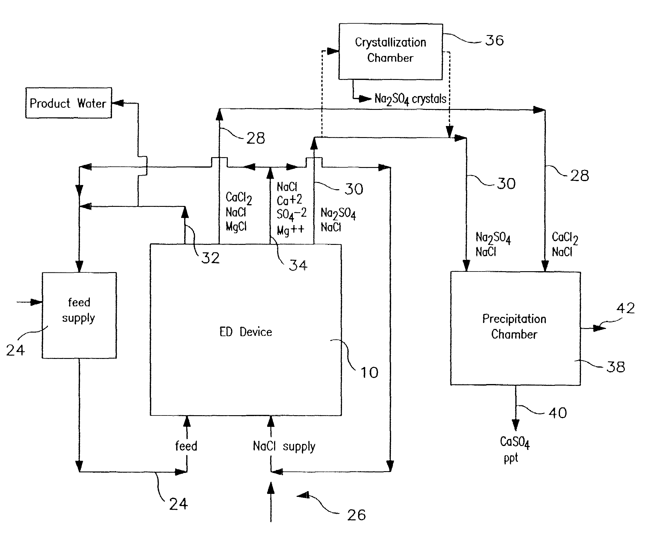
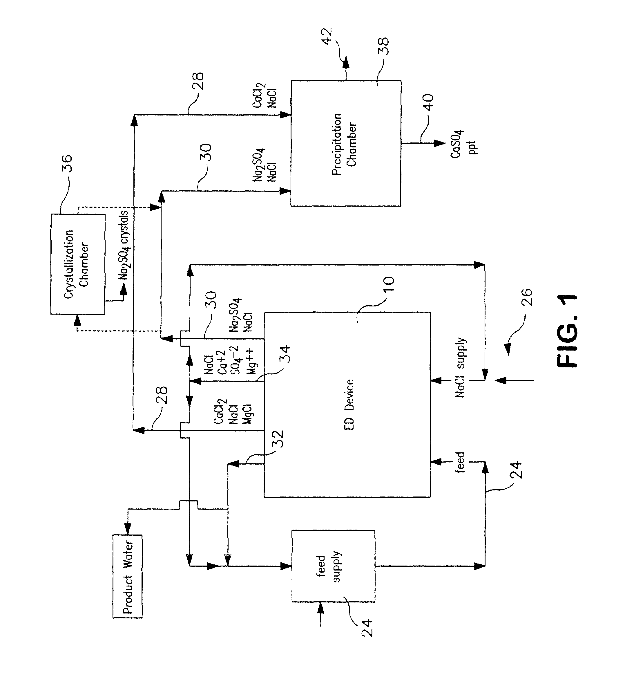
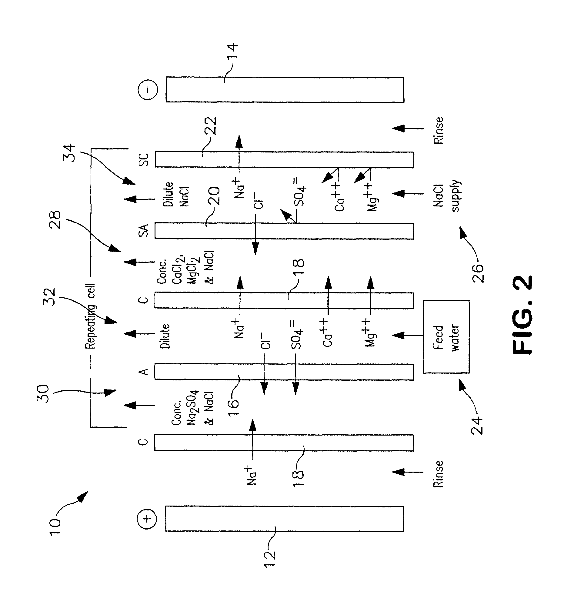
[0106]The following is a prophetic example illustrating the use of a system made in accordance with the present disclosure as particularly illustrated in FIGS. 1, 2 and 3. Specifically, the following are estimated calculations using the system and process of the present disclosure in order to desalinate groundwater obtained from the Tularosa Basin in New Mexico.

[0107]The ionic composition of real brackish water is unlikely to be just NaCl and CaSO4. An example of real brackish well water is groundwater from the Tularosa Basin in New Mexico. A reported ionic composition of that water is shown in Table 1, first as milligrams per liter, then as milliequivalents per liter.

[0108]

TABLE 1Treatment of Tularosa RO reject by ElectrodialysisIonHCO3−Cl−SO4=Na+Mg++Ca++totalFlowFeedwater analysis, mg / li27017013701141634202507Feedwater ions, meq / li4.434.7928.544.9613.4020.9638After lime softening, meq / li0.34.9929.724.9613.4016.6535RO feed neutralized, meq / li04.9930.024.9613.4016.65351000RO permeat...


PUM

PropertyMeasurementUnit
flow rateaaaaaaaaaa
specific gravityaaaaaaaaaa

Abstract

A process and system for purifying water is disclosed. For example, in one embodiment, the process may be used to remove a divalent salt, such as calcium sulfate, from a water source in order to prevent the divalent salt from precipitating during the process. The water source, for instance, may be fed to an ion separating device, such as an electrodialysis device. In the electrodialysis device, an ion exchange takes place between the divalent salt and another salt, such as a monovalent salt to produce two concentrated salt streams that contain salts having greater solubility in water than the divalent salt. In one embodiment, the two salt streams that are produced may then be combined to precipitate the divalent salt in a controlled manner. During the process, various other components contained within the water feed stream may also be removed from the stream and converted into useful products. In one particular embodiment, the process is configured to receive a byproduct stream from a reverse osmosis process.

Description

RELATED APPLICATIONS[0001]The present application is based upon and claims priority to U.S. Provisional Patent Application No. 60 / 609,404, filed on Sep. 13, 2004; U.S. Provisional Patent Application No. 60 / 651,819, filed on Feb. 10, 2005; U.S. Provisional Patent Application No. 60 / 664,223, filed on Mar. 22, 2005; and U.S. Provisional Patent Application No. 60 / 683,936, filed on May 23, 2005.BACKGROUND OF THE INVENTION[0002]As population grows, the strain on the world's fresh water supplies will increase. Factors such as a pleasant climate and mineral resources, job growth and rising incomes contribute to population growth. By 2025, about 2.7 billion people, nearly one-third of the projected population, will live in regions facing severe water scarcity. Many prosperous and fast growing regions—the American Southwest, Florida, Asia, the Middle East—have inadequate freshwater supplies. The water needs of municipalities, industry, and citizens must be met, even as the difficulty and cost...

Claims


Application Information

Patent Timeline
Patent Type & Authority Patents(United States)
IPC IPC(8): B01D61/44B01D61/02B01D61/42B01D61/46
CPCB01D61/022B01D61/025B01D61/027B01D61/44B01D61/445B01D61/48B01D61/52B01D61/58C01D3/06C01F11/46C02F1/441C02F1/469C02F1/5236B01D61/422C02F1/4693C02F5/00C02F2101/103C02F2103/08Y02A20/131Y02A20/124B01D61/423B01D61/029
Inventor DAVIS, THOMAS A.
Owner SOUTH CAROLINA THE UNIV OF
Learn More