
Adaptive segmentally controlled tunnel illumination control system and method

A tunnel lighting control and segmented control technology, applied in the field of tunnel lighting, can solve the problems of difficult tunnel brightness adjustment, complicated wiring, and high cost, and achieve the effects of satisfying visual comfort, simple control system, and small amount of installation engineering.

Inactive Publication Date: 2015-12-23
FUJIAN CHUANZHENG COMM COLLEGE
View PDF10 Cites 25 Cited by
  • Summary
  • Abstract
  • Description
  • Claims
  • Application Information

AI Technical Summary

Problems solved by technology

[0009] Disadvantage 1: The logic switch method cannot realize stepless dimming, and it is difficult to truly realize tunnel brightness adjustment that conforms to the brightness adaptation curve of the human eye
[0010] Disadvantage 2: Using PLC to control tunnel lighting is limited by the number of I / O control points, and it is difficult to simulate dimming. High-end PLC is required to achieve better control effect, but the cost is high
[0011] Disadvantage 3: The currently used dedicated controller realizes the segmented lighting wireless control method, which requires the cooperation of multiple controllers, and the circuit is more complicated
Moreover, the length and quantity of each lighting section are fixed, and the adaptability to changes in external factors is poor
[0012] Disadvantage 4: Using GPRS, WIFI and other wireless transmission methods to realize the data transmission of each lighting segment in the tunnel, the cost is high, the networking is inconvenient, and it depends on the external operator signal, which cannot be applied in remote areas

Method used


Image

  • Adaptive segmentally controlled tunnel illumination control system and method
  • Adaptive segmentally controlled tunnel illumination control system and method
  • Adaptive segmentally controlled tunnel illumination control system and method

Examples


Embodiment Construction

[0051] The technical solution of the present invention will be specifically described below in conjunction with the accompanying drawings.

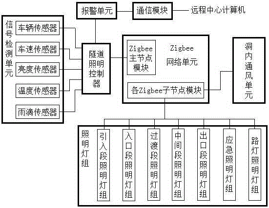
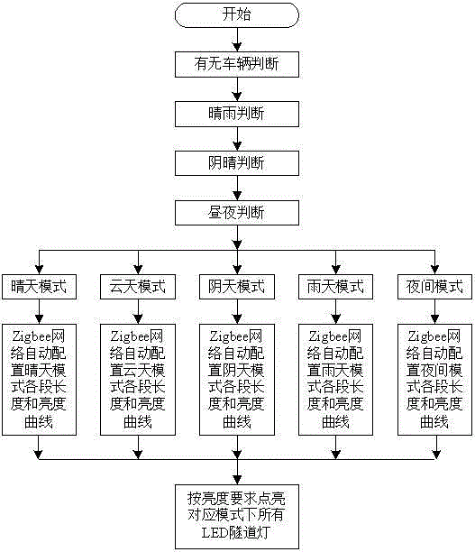
[0052] Such as Figures 1 to 2 As shown, a tunnel lighting control system for self-adaptive segmentation control in the present invention includes a tunnel lighting controller (the tunnel lighting controller uses an ARM microprocessor) and a signal detection unit connected to the tunnel lighting controller, Zigbee A network unit and an alarm unit, the alarm unit is also connected with a communication module connected with the remote central computer, and also includes several lighting lamp groups and ventilation units in the cave;

[0053] The signal detection unit includes a vehicle sensor for detecting whether a vehicle passes through the tunnel, a vehicle speed sensor for detecting the speed of vehicles passing through the tunnel, a brightness sensor for detecting brightness changes outside the tunnel, a temperature sensor for detectin...


PUM


Abstract

The invention relates to an adaptive segmentally controlled tunnel illumination control system and method; the system comprises a tunnel illumination controller, a signal detection unit, a Zigbee network unit, and a plurality of illumination lamp sets; the signal detection unit comprises a vehicle sensor, a vehicle speed sensor, a brightness sensor, a temperature sensor, and a raindrop sensor; the Zigbee network unit comprises Zigbee main node module connected with the tunnel illumination controller, and a plurality of Zigbee node modules respectively connected with the illumination lamp sets; the illumination lamp sets comprise an introduction segment lamp set arranged outside the tunnel, an illumination lamp set arranged in the entrance segment in the tunnel, a transition segment illumination lamp set, a middle segment illumination lamp set, an exit segment illumination lamp set, and a road lamp illumination lamp set arranged outside the tunnel, and also comprise an emergency illumination lamp set. The adaptive segmentally controlled tunnel illumination control system can realize tunnel illumination, satisfies illumination curve demands of human eyes, thus eliminating black frame, black hole and white hole effects.

Description

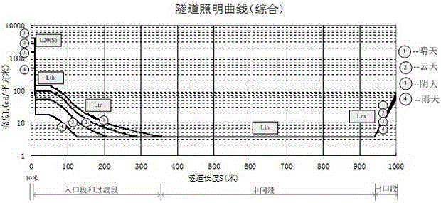
technical field [0001] The invention relates to the field of tunnel lighting, in particular to highway tunnel lighting, in particular to a tunnel lighting control system and method for self-adaptive section control. Background technique [0002] The tunnel is a special section of the road, especially during the use of the tunnel, the external brightness of the tunnel changes greatly with the change of time and weather. As vehicles drive into, through and out of tunnels, a series of visual problems can arise. When passing through a long tunnel, when the vehicle enters the tunnel, it will feel that the hole is so dark that it is impossible to recognize the situation near the hole, and even the obstacles cannot be recognized, resulting in a "black hole" effect. When the vehicle approaches the exit of the tunnel, what it sees is a dazzling white hole. At this time, the "white hole" effect is formed, which will also reduce the driver's visual function and visual comfort when exi...

Claims


Application Information

Patent Timeline
Patent Type & Authority Applications(China)
IPC IPC(8): H05B37/02
Inventor 陈常晖任慧潘燕燕朱其祥陈自力黄炳乐陈明
Owner FUJIAN CHUANZHENG COMM COLLEGE
Learn More