A device and method for measuring cable force of a short boom based on magnetostrictive guided wave
What is Al technical title?
Al technical title is built by PatSnap Al team. It summarizes the technical point description of the patent document.
A measuring device and short boom technology, which is applied in the direction of tension measurement and the measurement of the change force of the magnetic property of the material caused by the applied stress, can solve the problems of complicated installation, inconvenient use, large error, etc., and speed up the efficiency , easy to carry and install, light weight effect
Inactive Publication Date: 2017-06-20
HUAZHONG UNIV OF SCI & TECH
View PDF11 Cites 0 Cited by
Summary
Abstract
Description
Claims
Application Information
AI Technical Summary
This helps you quickly interpret patents by identifying the three key elements:
Problems solved by technology
Method used
Benefits of technology
Problems solved by technology
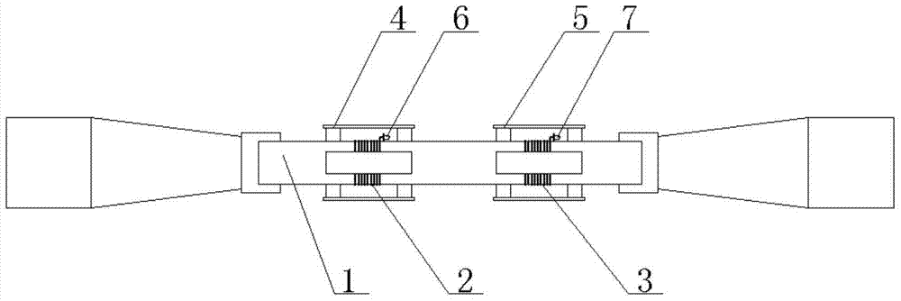
[0005] In order to overcome the problems of large errors, complicated installation, and inconvenient use in the prior art, the present invention provides a cable force measuring device based on magnetostrictive guided waves for short booms, including an excitation bias magnetizer and a receiving bias magnetizer. , an exciting coil, a receiving coil, and a guided wave measuring instrument, characterized in that:
Method used
Image
Click on the blue label to locate the original text in one second.
Reading with bidirectional positioning of images and text.
Examples
Embodiment Construction
[0029] In order to make the object, technical solution and advantages of the present invention clearer, the present invention will be further described in detail below in conjunction with the accompanying drawings and embodiments. It should be understood that the specific embodiments described here are only used to explain the present invention, not to limit the present invention.
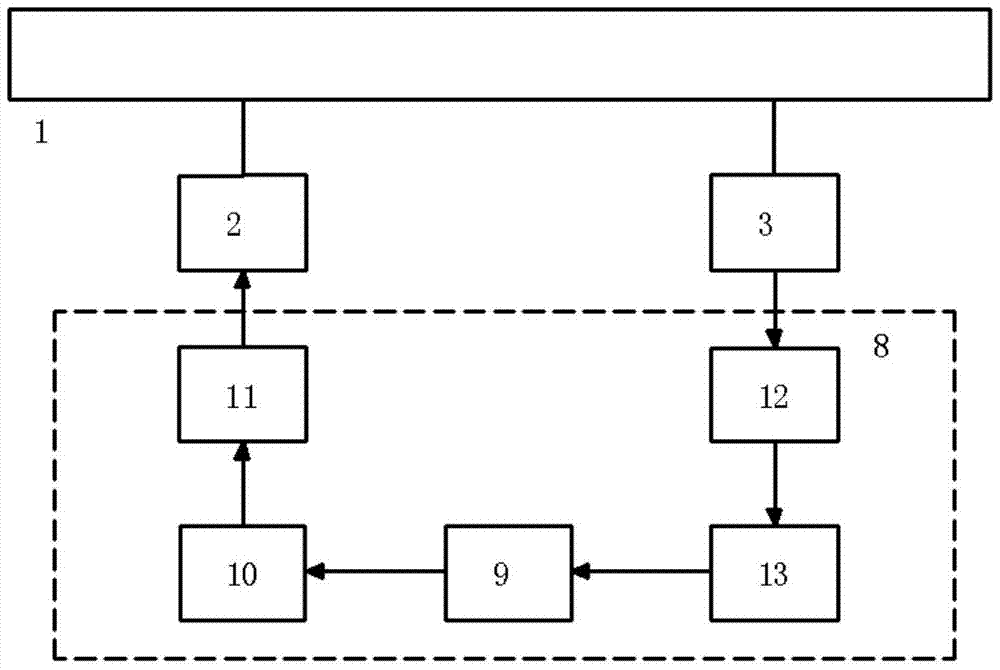
[0034] figure 2It shows a structural block diagram of cable force measurement using the magnetostri...
PUM
Abstract
The invention relates to a magnetostriction-guide-wave-based measurement apparatus and method of a short suspender cable force. The apparatus is composed of an excitation bias magnetizer, a receiving bias magnetizer, an excitation coil, a receiving coil, and a guide wave measuring instrument. According to the magnetostrictive effect principle, excitation is carried out inside the short suspender by the excitation coil for long timer to form steady-state vibration; and an induction signal is obtained at the receiving coil based on a counter-magnetostrictive effect and the induction signal is analyzed and calculated to obtain a short suspender cable force. According to the method, with long-time frequency excitation by a magnetostrictive guide wave, the steady-stage vibration is generated in the short suspender; after excitation, vibration signals of the short suspender during the period from the excitation suspending to attenuation to zero are extracted and spectral analyses are carried out to obtain a longitudinal inherent frequency of the short suspender; and on the basis of the correspondence relation of the longitudinal inherent frequency and the cable force, the cable force value of the short suspender is obtained. With the apparatus and method, the cable force measurement is free from limitation of the short suspender boundary condition and the flexural rigidity, so that the measurement becomes convenient; and the measurement repeatability is high.
Description
technical field [0001] 本发明属于桥梁缆索测量技术领域,更具体地,涉及一种短吊杆索力测量方法及装置。 Background technique [0002] 在现代桥梁建设中,缆索所承载应力我们称为“索力”,索力测量是极其重要的一项工作,拉索的受力状态在桥梁施工和运营过程的健康评估中起着至关重要的作用,要求得到精确的测试结果,以保证桥梁的运营安全。 [0003] 目前常用的索力测量方法主要有磁通量测量法以及频率振动测量法。磁通量测量法受温度影响明显,必须对温度作用进行校正。电磁传感器必须套在拉索的外面,拉索直径种类众多,不同拉索需要相对应电磁传感器。频率振动测量法是利用吊杆索力大小与吊杆的振动频率间的确定关系,通过实测吊杆的振动频率来分析计算吊杆的索力大小。对于较长的吊杆,常规频率法的索力测量精度是可以满足工程要求的。但是,在吊杆拱桥中,位于桥梁拱脚附近的吊杆,通常长度很短,此时吊杆的锚固条件、护筒、减震器、吊杆刚度等因素会对吊杆频率产生较大影响,而这种影响的大小往往很难确定,这时采用常规的频率振动测量法测得的吊杆索力误差很大,存在较大的误判可能性,甚至得出错误的结果。因此,在对吊杆拱桥这一类有短吊杆的桥型中,急需一种能够精确测定短吊杆索力的方法。通常将小于等于5米的吊杆称为短吊杆。 [0004] 申请号201310573666.1公布了一种短吊杆拱桥短吊杆索力精确测试方法,需要对吊杆进行附加质量块前后两次振动频率测试。需要对吊杆增加两次质量块,质量块质量较大且为磁性铁块,不便现场操作。申请号201310156134.8公布了一种基于光学测量原理的短吊杆索力测量方法与装置。此装置安装复杂,现场检测时需要现场对温度进行标定,还需对吊杆销轴进行开孔,给现场测量带来不便。 Contents of the invention [0005] 为了克服现有技术存在误差较大、安装复杂、使用不方便等问题,本发明提供一种基于磁致伸缩导波短吊杆索力测量装置,包括激励偏置磁化器、接收偏置磁化器、激励线圈、接收线圈、导波测量仪,其特征在于: [0006] 工作中,所述激励线圈和接收线圈同轴套装在待测短吊杆上,所述激励偏置磁化器和接收偏置磁化器结构相同,分别安装在待测短吊杆两端,分别与待测短吊杆形成磁闭合回路,提供饱和的...
Claims
Application Information
Patent Timeline
Application Date:The date an application was filed.
Publication Date:The date a patent or application was officially published.
First Publication Date:The earliest publication date of a patent with the same application number.
Issue Date:Publication date of the patent grant document.
PCT Entry Date:The Entry date of PCT National Phase.
Estimated Expiry Date:The statutory expiry date of a patent right according to the Patent Law, and it is the longest term of protection that the patent right can achieve without the termination of the patent right due to other reasons(Term extension factor has been taken into account ).
Invalid Date:Actual expiry date is based on effective date or publication date of legal transaction data of invalid patent.