
Energy-harvesting-circuit-based piezoelectric-electromagnetic composite energy harvesting device

A technology of energy harvesting and piezoelectric energy harvesting, applied in current collectors, piezoelectric effect/electrostrictive or magnetostrictive motors, circuit devices, etc., can solve the problem of not being able to output large voltage and large current at the same time, and different working principles and other problems, to achieve the effect of avoiding the large volume of battery power supply, convenient operation and control, and strong environmental adaptability

Active Publication Date: 2015-12-16
BEIJING INSTITUTE OF TECHNOLOGYGY
View PDF11 Cites 17 Cited by
  • Summary
  • Abstract
  • Description
  • Claims
  • Application Information

AI Technical Summary

Problems solved by technology

The working principles of piezoelectric and electromagnetic energy harvesters are different, and they cannot output large voltage and high current at the same time

Method used


Image

  • Energy-harvesting-circuit-based piezoelectric-electromagnetic composite energy harvesting device
  • Energy-harvesting-circuit-based piezoelectric-electromagnetic composite energy harvesting device
  • Energy-harvesting-circuit-based piezoelectric-electromagnetic composite energy harvesting device

Examples


Embodiment 1

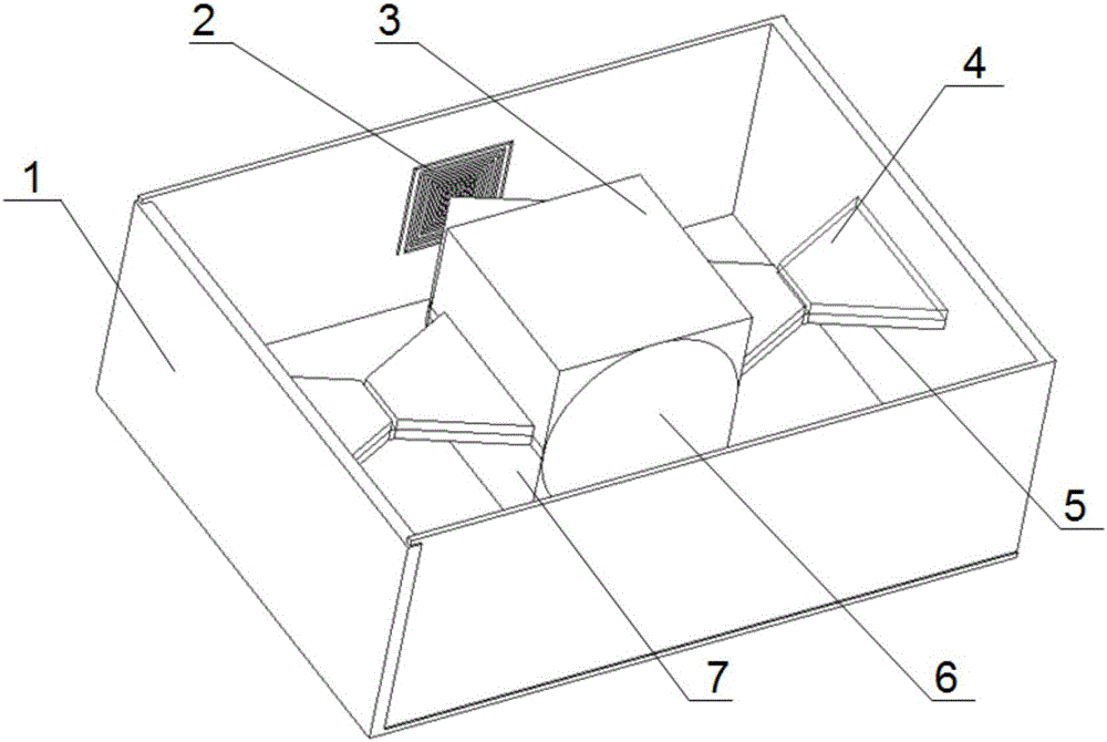
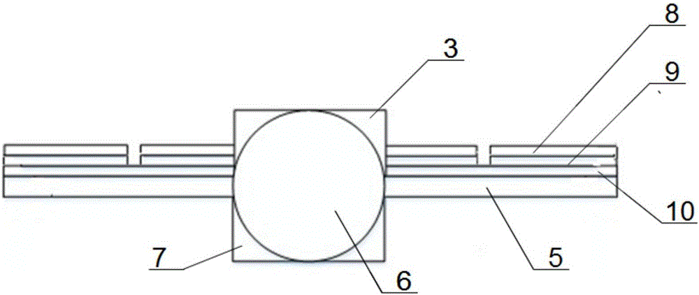
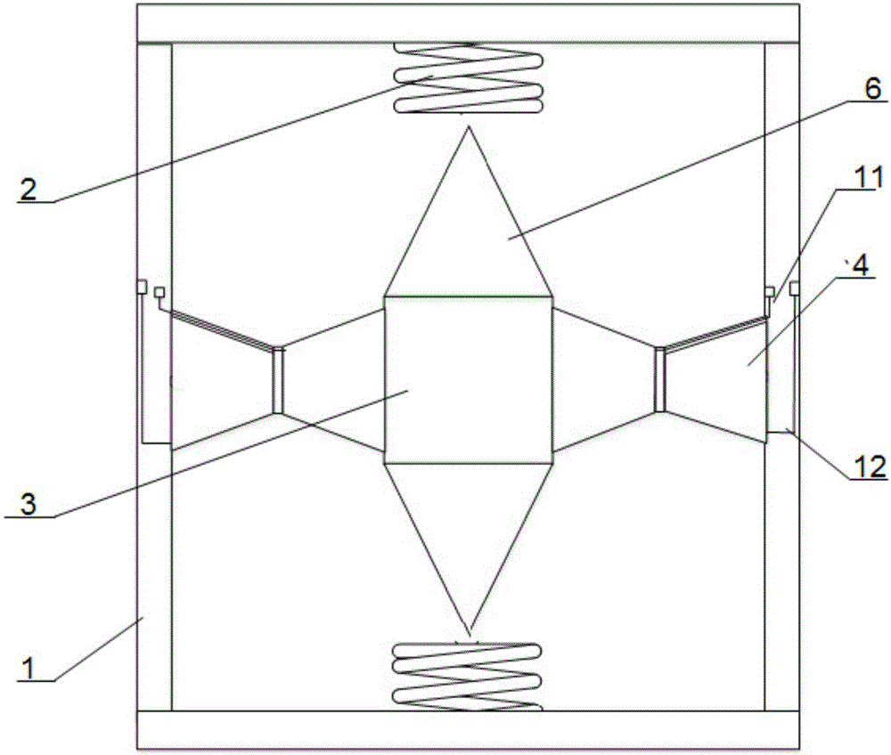
[0045] Such as figure 1 , 2 , 3, a piezoelectric-electromagnetic composite energy harvester based on an energy harvesting circuit disclosed in this embodiment includes a piezoelectric-electromagnetic composite energy harvester and a piezoelectric-electromagnetic composite energy harvester for controlling energy harvesting circuit.

[0046] The piezoelectric-electromagnetic composite energy harvester includes a housing 1, a coil 2, an upper permanent magnet 3, a piezoelectric ceramic material 4, a base beam 5, a tapered permanent magnet 6, a lower permanent magnet 7, an upper electrode 8, The piezoelectric sheet 9, the lower electrode 10, the lead wire 11 of the upper electrode on the left piezoelectric sheet, and the lead wire 12 of the upper electrode on the right piezoelectric sheet. Coils 2 are symmetrically distributed on both sides of the inner wall of the housing 1, the coils 2 are perpendicular to the bottom surface of the housing 1, the coils 2 are fixedly connected ...


PUM


Abstract

Disclosed in the invention is an energy-harvesting-circuit-based piezoelectric-electromagnetic composite energy harvesting device. The invention relates to a piezoelectric-electromagnetic composite energy harvesting device capable of improving an output power, which belongs to the technical field of the new energy and power generation. The piezoelectric-electromagnetic composite energy harvesting device comprises a piezoelectric-electromagnetic composite energy harvesting device body and an energy collection circuit. The piezoelectric-electromagnetic composite energy harvesting device body consists of a housing, a coil, an upper permanent magnet, a piezoelectric ceramic material, a foundation beam, a tapered permanent magnet, a lower permanent magnet, an upper electrode, a piezoelectric plate, a lower electrode, a left piezoelectric plate upper electrode lead, a right piezoelectric plate upper electrode lead. The energy collection circuit includes an electromagnetic energy harvesting device energy collection circuit, a piezoelectric energy harvesting device energy collection circuit, and a charging circuit for realizing composite charging and preventing current returning. According to the invention, conversion from an alternating current to a direct current is realized; the output power supply is improved for a load. The energy harvesting device has advantages of green and pollution-free effects, high energy density, shortened charging time, high reliability, high environment adaptability, convenient operation control, and low maintenance cost and the like.

Description

technical field [0001] The invention relates to a piezoelectric-electromagnetic composite energy harvester, in particular to a piezoelectric-electromagnetic composite energy harvester that improves output power based on an energy harvesting circuit under environmental vibration conditions, and belongs to the technical field of new energy and power generation. Background technique [0002] Currently, known power supply elements are generally chemical batteries. The chemical battery has limited energy storage and needs to be replaced regularly, and the cost of manpower and material resources is high. [0003] The known measurement and control systems all need external power supply, and the external power supply and the sensor must be connected by wires, and the wiring is complicated and convenient; and it cannot be used in an environment without power supply or in an extremely harsh environment (such as the energy supply of an oil drilling drill bit positioning sensor). Exter...

Claims


Application Information

Patent Timeline
Patent Type & Authority Applications(China)
IPC IPC(8): H02N2/18H02K35/00H02J7/32
CPCH02J7/32H02K35/00H02N2/181H02N2/186
Inventor 刘海鹏高世桥张广义武丽森谭杨康王子文王学敏
Owner BEIJING INSTITUTE OF TECHNOLOGYGY
Learn More