Tube bending machine applied to steel tube production

A pipe bending machine and steel pipe technology, which is applied in the field of pipe bending machines, can solve the problems affecting the normal bending and bending accuracy of steel pipes, reduce production efficiency, and low efficiency, and achieve the solution of steel pipe bending problems, high degree of automation, and simple machine structure Effect

Active Publication Date: 2015-12-16
嵊州市恒鑫金属制管有限公司
View PDF6 Cites 3 Cited by
  • Summary
  • Abstract
  • Description
  • Claims
  • Application Information

AI Technical Summary

Problems solved by technology

Pipe benders are mainly used for bending steel pipes and other materials, and play an important role in the laying and repair of pipes in boilers, bridges, ships, furniture, decoration, etc. Due to the limitation of the mold, the arc cannot be bent at will. For example, if it is a perfect circular mold, the curved arc can only be a perfect circle, but not an elliptical arc. If you want to bend other arcs, you can only change the mold. It causes waste of materials and increases in cost, and also reduces production efficiency.
In addition, due to the influence of the structure, the traditional pipe bending machine can only process flat products, the efficiency is low, the product quality is unstable, and it is not suitable for mass production; the scope of use is small, and it cannot meet the existing diversified products, such as steel pipes and clamping devices. The contact point with the bending table is prone to slipping, which affects the normal bending and bending accuracy of the steel pipe

Method used


Image

  • Tube bending machine applied to steel tube production
  • Tube bending machine applied to steel tube production
  • Tube bending machine applied to steel tube production

Examples


Embodiment Construction

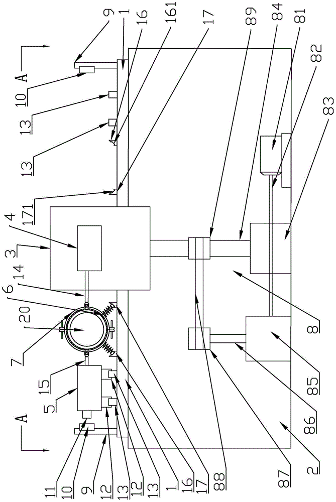
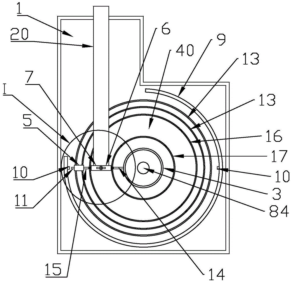
[0030] like Figure 1 to Figure 8 As shown, a pipe bending machine used in the production of steel pipes includes a frame 2 and a workbench 1. The workbench 1 is located on the frame 2, and the workbench 1 is provided with a bending guide rail 13 and a bending table 3. The outside of the workbench 1 is provided with an arc-shaped photoelectric switch fixing plate 9, and the arc-shaped photoelectric switch fixing plate 9 is provided with a photoelectric switch 10, and the side of the outer clamping control room 5 is provided with a stopper 11, and the photoelectric switch 10 and the stopper 11 matches. By installing the arc-shaped photoelectric switch fixing plate 9 on the outside of the bending table 3, when the bent pipe 20 enters the bending space 40, the photoelectric switch 10 sends a signal to start working, and immediately starts the first cylinder 41 and the second cylinder of the clamping device 42. Clamp the pipe 20 to be bent, and reflect the degree of clamping thro...


PUM


Abstract

The invention discloses a tube bending machine applied to steel tube production. The tube bending machine comprises a machine frame and a working table. The working table is located on the machine frame. A bent guide rail and a bent table are arranged on the working table. A clamping device is connected between the bent table and the bent guide rail and comprises clamping control chambers and clamping bases. The clamping control chambers comprise the inner clamping control chamber and the outer clamping control chamber. The clamping bases comprise the inner clamping base and the outer clamping base. A bent sliding block is arranged on the bent guide rail, the upper end of the bent sliding block is connected with the outer clamping control chamber, and the outer clamping control chamber is fixedly installed on the bent sliding block. The inner clamping base is connected with an inner arc inclined rail. The outer clamping base is connected with an outer arc inclined rail. A rotating shaft is arranged at the lower end of the bent table and connected with a power driving device. Through the clamping device, the inner clamping base and the outer clamping base cooperate to clamp a tube to be bent so as to make preparations for bending the tube to be bent; through the bent guide rail and the bent sliding block, the outer clamping chamber can work along with the outer clamping base in the process of bending the tube to be bent.

Description

technical field [0001] The invention relates to a pipe bending processing equipment, in particular to a pipe bending machine used in the production of steel pipes. Background technique [0002] Pipe bending machines can be roughly divided into CNC pipe bending machines, hydraulic pipe bending machines and so on. Pipe benders are mainly used for bending steel pipes and other materials, and play an important role in the laying and repair of pipes in boilers, bridges, ships, furniture, decoration, etc. Due to the limitation of the mold, the arc cannot be bent at will. For example, if it is a perfect circular mold, the curved arc can only be a perfect circle, but not an elliptical arc. If you want to bend other arcs, you can only change the mold. It causes the waste of materials and the increase of cost, and also reduces the production efficiency. In addition, due to the influence of the structure, the traditional pipe bending machine can only process flat products, the effici...

Claims


Application Information

Patent Timeline
IPC IPC(8): B21D7/08
Inventor 张天行吴健浩
Owner 嵊州市恒鑫金属制管有限公司
Why Eureka
Try Eureka