
A selective sintering flue gas segmented comprehensive treatment process

A technology for sintering flue gas and comprehensive treatment, applied in waste heat treatment, furnace, lighting and heating equipment, etc., can solve the problems of equipment investment and operation, waste of site occupation, rising construction investment and operation cost, single function, etc., to reduce construction costs. The effect of investment and production operation costs, reduction of investment and operation costs, and improvement of economic benefits

Active Publication Date: 2017-08-29
郑琨
View PDF5 Cites 0 Cited by
  • Summary
  • Abstract
  • Description
  • Claims
  • Application Information

AI Technical Summary

Problems solved by technology

[0006] To sum up, the current control and removal methods of sintering flue gas pollutants are mostly terminal treatment processes with a single function. With the increase of pollutant emission restrictions, the terminal treatment process facilities can only be more and more, occupying more and more land. The larger the size, the higher the construction investment and operating costs; the waste heat of the sintering process is also recycled from a single part, which also causes waste in equipment investment and operation, site occupancy, etc.

Method used


Image

  • A selective sintering flue gas segmented comprehensive treatment process
  • A selective sintering flue gas segmented comprehensive treatment process

Examples


Embodiment

[0036] Take a certain 210m 2 Taking a sintering machine as an example, a detailed description of a selective sintering flue gas segmented comprehensive treatment process of the present invention is as follows:

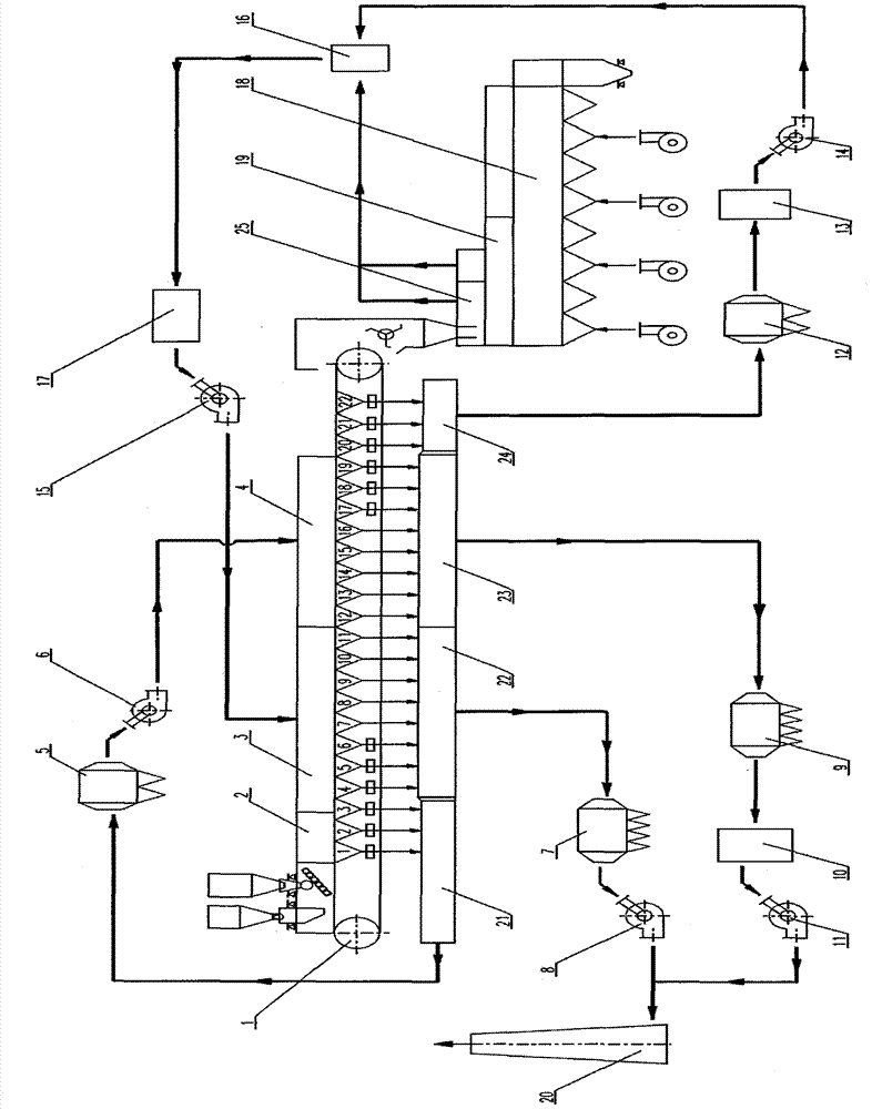
[0037] Such as figure 1 shown in a 210m 2 On the sintering machine 1, the sintering flue gas from the No.1-No.3 bellows in the ignition area of ​​the sintering machine head in the area ① is collected into the flue gas pipeline of the machine head, and then passes through the multi-pipe dust collector 5 of the machine head and the circulating fan 6 of the machine head Lead to the flue gas circulation hood 4 of the sintering machine 1 for flue gas circulation and sintering; collect the sintering flue gas from No.4 to No.11 bellows in the area ② in the middle of the sintering machine where the flue gas is discharged directly into the direct flue gas pipeline The sintering electrostatic precipitator 7 is led by the sintering main exhaust fan 8 to the sintering main chimn...


PUM


Abstract

The invention discloses a selective sintering flue gas sectional type comprehensive treatment technology, and belongs to the technical field of energy conservation and environmental protection. Flue gas circulation sintering is performed on ignition section flue gas with the high SO2 concentration and the low NOx concentration at a sintering head part; dust removal and desulfurization are performed on flue gas with the high SO2 concentration at a sintering middle part and then the flue gas is exhausted out; dust removal is performed on flue gas with the low SO2 concentration and the low NOx concentration at the sintering middle part and then the flue gas is exhausted out; dust removal and denitrification are performed on flue gas with the low SO2 concentration and the high NOx concentration at a sintering tail part, then the flue gas is mixed with flue gas at a high temperature section of a cooler, and waste heat recovery is performed; heated air circulation sintering is performed on the recycled hot flue gas; and steam generated after waste heat recycling can be used for waste heat power generation or steam-driving sintering of a main suction fan. According to the selective sintering flue gas sectional type comprehensive treatment technology, sintering flue gas section desulfurization and denitrification are achieved, and the flue gas discharge amount is decreased; and the flue gas waste heat recycling efficiency is improved, the construction investment and production running cost are lowered on the whole, and the selective sintering flue gas sectional type comprehensive treatment technology conforms to the energy-saving, environment-friendly, emission reduction, consumption reduction, efficiency increase and recycling economic running mode.

Description

technical field [0001] The invention belongs to the technical field of energy saving, environmental protection, emission reduction and consumption reduction in the sintering production process of the iron and steel metallurgy industry, and relates to a segmented comprehensive treatment process for sintering flue gas desulfurization and denitrification and cascade utilization of flue gas waste heat, in particular to a selective sintering process A comprehensive treatment process for flue gas segmental desulfurization and denitrification, hot air circulation sintering, and waste heat recovery and utilization of flue gas, more specifically involving a SO 2 , NO x , CO x A selective sintering flue gas segmented comprehensive treatment process with concentration distribution characteristics. Background technique [0002] The iron and steel industry is a major energy consumer and also a major polluter. The sintering process is one of the main sources of air pollutants in the iro...

Claims


Application Information

Patent Timeline
Patent Type & Authority Patents(China)
IPC IPC(8): F27D17/00
Inventor 郑琨
Owner 郑琨
Learn More