Assembled monolithic concrete frame structure system and frame shear structure system formed by assembled monolithic concrete frame structure system

A frame structure and concrete technology, used in building components, building structures, walls, etc., can solve the problems that the seismic resistance and overall performance of the structure cannot be fully guaranteed, cannot effectively prevent cross-inclined cracks, and affect the safe use of high-rise buildings. The effect of saving splicing time, convenient construction and simple connection structure

Inactive Publication Date: 2015-12-09
ZHENGZHOU UNIV
View PDF8 Cites 5 Cited by
  • Summary
  • Abstract
  • Description
  • Claims
  • Application Information

AI Technical Summary

Problems solved by technology

[0003] However, the existing prefabricated concrete frame and frame-shear structure buildings have many deficiencies that limit the promotion and application of this type of structure.
For example, the prefabricated components are all solid concrete rods, the structure has a large dead weight, wastes building materials, and has higher requirements for construction machinery and hoisting equipment; the beam-column joints do not transmit force directly, and the reliability is poor, resulting in earthquake resistance and The overall performance cannot be fully guaranteed; in order to increase the seismic performance of the structure, many nodes are set as cast-in-place nodes. There are horizontal and vertical steel bars, which cannot effectively prevent the occurrence and development of cross-slanted cracks along the principal stress direction during use, resulting in the degradation of the stiffness of the shear wall structure and the reduction of bearing capacity, and even affect high-rise buildings in severe cases safe use, etc.

Method used


Image

  • Assembled monolithic concrete frame structure system and frame shear structure system formed by assembled monolithic concrete frame structure system
  • Assembled monolithic concrete frame structure system and frame shear structure system formed by assembled monolithic concrete frame structure system
  • Assembled monolithic concrete frame structure system and frame shear structure system formed by assembled monolithic concrete frame structure system

Examples


Embodiment 1

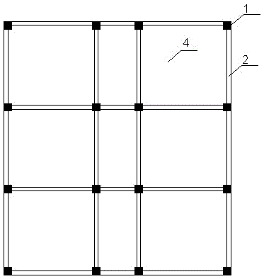
[0052] Depend on Figure 1-Figure 7 An assembled monolithic concrete frame structure system shown includes prefabricated columns 1 , prefabricated beams 2 and prefabricated floor slabs 4 . Wherein the prefabricated column 1 is arranged vertically, and the prefabricated beam 2 and the prefabricated floor slab 4 are both arranged horizontally. Prefabricated columns 1 and prefabricated beams 2 form a frame body, several prefabricated columns 1 are arranged vertically and horizontally at intervals, and several prefabricated beams 2 are respectively arranged between two vertically adjacent precast columns 1 and between horizontally adjacent two prefabricated columns. The floor slab 4 is erected in the area enclosed by four prefabricated beams.

[0053] The prefabricated beam 2 is an ordinary reinforced concrete member, and the prefabricated beam 2 is provided with a prefabricated beam reinforcement cage 72, and a block-shaped prefabricated beam foam plastic inner mold 82 is embedded...

Embodiment 2

[0059] Depend on Figure 8-Figure 9 The difference between the assembled integral concrete frame structure system shown in Example 1 is that the prefabricated floor slab 4 adopts a prefabricated concrete hollow floor slab, and the prefabricated frame beams connected between the prefabricated columns 1 and the prefabricated beams 2 are connected by cover plates Column joint structural connection.

[0060] The ends of the prefabricated floor slabs 4 are erected on the top end faces of the corresponding prefabricated beams 2, and the prefabricated floor slabs 4 are formed by connecting several precast concrete hollow floor slabs 28 through end concrete transverse joints and slab side concrete longitudinal joints. The butt ends of the two precast concrete hollow slabs 28 are erected on the beam tops of the corresponding prefabricated beams 2, and a main grouting area 30 for concrete grouting is provided between the two butt ends of the two precast concrete hollow slabs 28, and the...

Embodiment 3

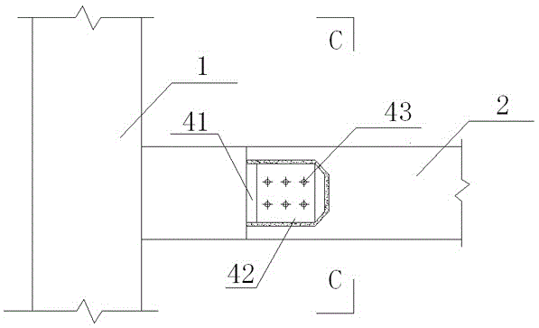
[0063] Depend on Figure 10-Figure 11 An assembled monolithic concrete frame structure system shown is different from Embodiment 1 or Embodiment 2 in that the prefabricated column 1 and the prefabricated beam 2 are connected through a fabricated frame beam-column node structure using transverse connections.

[0064] The assembled frame beam-column joint structure adopting horizontal connection includes the concealed corbel 41 set on the beam of the prefabricated column 1, the cross section of the concealed corbel 41 is rectangular, and the concealed corbel bolt holes are reserved horizontally on the concealed corbel 41; the prefabricated The front side of the joint of the end of the beam 2 is provided with a notch groove matched with the concealed corbel 41. The notch groove is to dig a gap from the vertical axis of the prefabricated beam 2 to one side, and the cross-sectional shape of the notch and the concealed corbel 41 Similarly, the size of the notch is slightly larger th...


PUM


Abstract

The invention discloses an assembled monolithic concrete frame structure system and a frame shear structure system formed by the assembled monolithic concrete frame structure system. The assembled monolithic concrete frame structure system comprises precast columns, precast beams and precast floors, wherein the precast beams and the precast columns are connected to form a frame structure; the precast floors are arranged on the frame structure in an overlapping manner and are connected with the precast beams. The assembled monolithic concrete frame shear structure system comprises the assembled monolithic concrete frame structure system and precast sheer walls. According to the assembled monolithic concrete frame structure system and the frame shear structure system formed by the assembled monolithic concrete frame structure system, building materials can be saved, the structure self-weight is reduced, the construction speed is increased, the production efficiency is improved, the precast sheer wall bodies and seam construction are improved, the appearance and development of inclined cracks of the precast sheer wall bodies are reduced, and the anti-seismic working performance of the precast concrete frame structure system and the frame shear structure system formed by the precast concrete frame structure system is effectively enhanced.

Description

technical field [0001] The invention belongs to the technical field of assembled concrete buildings, and in particular relates to an assembled integral concrete frame structure system and a frame-shear structure system formed therefrom. Background technique [0002] Prefabricated concrete building is an important way of building industrialization. It has many advantages such as fast construction speed, short construction period, high production efficiency, good product quality, safety and environmental protection, effective cost reduction, material consumption and construction process. Prefabricated concrete frame structure and frame-shear structure refer to the prefabrication of columns, beams, shear walls, floors and other components in the processing plant or construction site, and the scattered prefabricated components are connected into a whole through mechanical hoisting and certain connection means. formed structure. This structure has the advantages of good componen...

Claims


Application Information

Patent Timeline
IPC IPC(8): E04B1/00E04B1/20E04B1/21E04B5/14E04B5/17E04B2/64
Inventor 陈淮王艳葛素娟李杰陈代海李静斌黄亮张军峰李整
Owner ZHENGZHOU UNIV
Why Eureka
Try Eureka