
Integrated water lubrication bearing for thruster with hub flange

A water-lubricated bearing, integrated technology, applied in the direction of rotary propeller, propulsion power transmission, ship propulsion, etc., can solve the problems of reducing the bearing capacity of the thrust plate, poor lubrication and cooling performance, and shortening the service life

Active Publication Date: 2015-12-09
WUHAN UNIV OF TECH +1
View PDF6 Cites 10 Cited by
  • Summary
  • Abstract
  • Description
  • Claims
  • Application Information

AI Technical Summary

Problems solved by technology

The lubricating and cooling water flowing into the radial bearing is very limited, and it is difficult to achieve the lubricating and cooling effect; although there is a flow channel on the propeller hub behind the thrust disc, the water flow is completely natural; in order to install the thrust disc on the propeller hub, Without destroying its thrust surface, a blind hole is processed on the surface opposite to the thrust surface, but this also increases the diameter of the propeller hub
[0003] The Chinese patent "Shaftless Driven Integrated Motor Propeller" (CN102632982A) also has a hub rim propeller. Its structure is simple, and the radial bearing is similar to the U.S. patent, but there is no separate lubricating water channel, and the lubricating and cooling performance is relatively poor, and In order to install the thrust plate on the propeller hub, a blind hole is opened on the thrust surface of the thrust plate, which destroys its working surface, which will reduce the bearing capacity of the thrust plate, increase the wear of the thrust pad, and shorten its life

Method used


Image

  • Integrated water lubrication bearing for thruster with hub flange
  • Integrated water lubrication bearing for thruster with hub flange
  • Integrated water lubrication bearing for thruster with hub flange

Examples


Embodiment Construction

[0031] The present invention will be further described below in conjunction with the embodiments and accompanying drawings, but the present invention is not limited.

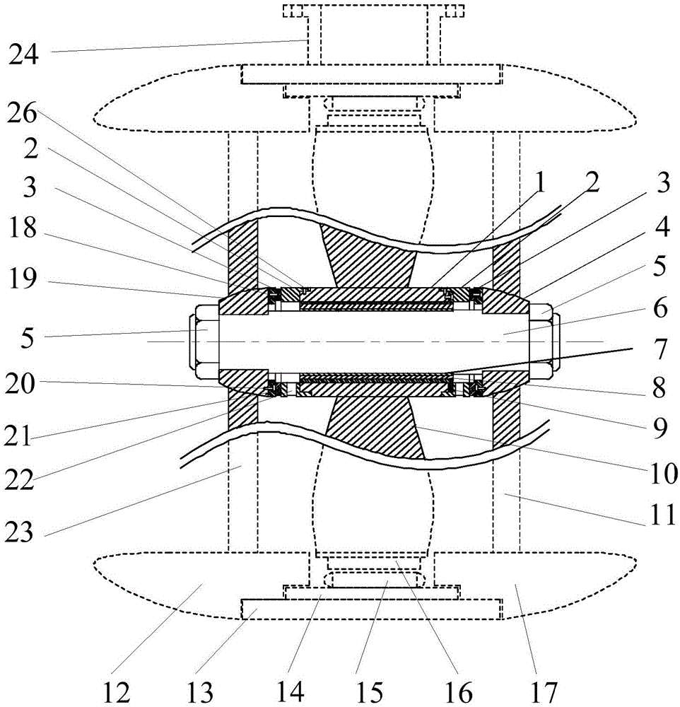
[0032] The integrated water-lubricated bearing used for hub rim propeller provided by the present invention has a structure such as figure 1 As shown, it is mainly composed of a thrust plate 2, a support ring 3, a shaft sleeve 7, a rubber slat 8, a propeller hub copper sleeve 9 and a thrust shoe 21. Among them: the propeller hub copper sleeve 9 is installed in the propeller hub from the front end of the propeller hub 1, there is a blind hole 25 on the front end surface of the propeller hub, and the end flange of the propeller hub copper sleeve 9 has a counterbore 28, which is used to prevent the propeller The locking bolt of the hub copper sleeve is higher than the flange surface to ensure the flatness of the flange end surface, so that the thrust disc 2 can be completely attached to the flange after it is insta...


PUM


Abstract

The invention discloses an integrated water lubrication bearing for a thruster with a hub flange. The integrated water lubrication bearing is mainly composed of thrust discs (2), supporting rings (3), a shaft sleeve (7), a rubber batten (8), a propeller hub copper sleeve (9) and thrust pads (21). The propeller hub copper sleeve is arranged in a propeller hub (1), the two thrust discs are installed at the two ends of the propeller hub respectively, spiral flow channels (22) are machined in the thrust discs, the two supporting rings are arranged on a front guide vane hub (4) and a rear guide vane hub (19) connected with a propeller shaft (6) respectively, and the thrust pads are assembled in fan-shaped grooves (33) in the supporting rings. The thrust pads (21), the thrust discs (2) and the supporting rings (3) form a thrust bearing. The rubber batten is vulcanized on the outer cylindrical surface of the shaft sleeve. The shaft sleeve (7), the rubber batten (8) and the propeller hub copper sleeve (9) form a combined radial bearing. The integrated water lubrication bearing has the advantages that the structure is simple and compact, the cooling effect of the radial bearing and the thrust bearing is improved, the bearing capacity of the radial bearing is improved, and the service life is prolonged.

Description

technical field [0001] The invention belongs to the field of ship propellers, and in particular relates to an integrated design and installation process of a combined radial bearing and a thrust bearing of a propeller with a hub rim. Background technique [0002] The rim thruster has attracted more and more attention due to its many advantages such as low vibration, low noise, and saving the interior space of the cabin. At present, the rim thruster has two forms: hubless and hubless. The U.S. patent "IntegralMotorPropulsorUnitForWaterVehicles" (US005220231A) is a hub rim propeller, the radial bearing is installed in the propeller hub, and the thrust bearing is installed on the propeller hub end face. The lubricating and cooling water flowing into the radial bearing is very limited, and it is difficult to achieve the lubricating and cooling effect; although there is a flow channel on the propeller hub behind the thrust disc, the water flow is completely natural; in order to i...

Claims


Application Information

Patent Timeline
Patent Type & Authority Applications(China)
IPC IPC(8): B63H1/16B63H5/14B63H23/24
Inventor 刘正林梁兴鑫严新平欧阳武王建
Owner WUHAN UNIV OF TECH
Learn More