Molten glass conduit structure, and device and method using conduit structure
What is Al technical title?
Al technical title is built by PatSnap Al team. It summarizes the technical point description of the patent document.
一种熔融玻璃、导管的技术,应用在玻璃炉设备、玻璃制造设备、制造工具等方向,达到削减制造成本的效果
Active Publication Date: 2015-12-02
AGC INC
View PDF8 Cites 7 Cited by
Summary
Abstract
Description
Claims
Application Information
AI Technical Summary
This helps you quickly interpret patents by identifying the three key elements:
Problems solved by technology
Method used
Benefits of technology
Problems solved by technology
[0021] The glass melting tank with such a structure has the same problems as the conduit structure for molten glass described above.
Method used
Image
Click on the blue label to locate the original text in one second.
Reading with bidirectional positioning of images and text.
Examples
Embodiment
[0161] Hereinafter, the present invention will be described more specifically based on examples. However, the present invention is not limited thereto.
[0162] In the examples shown below, the monolithic refractory (castable refractory) having the composition shown in Table 1 was used for the monolithic refractory layer.
[0163] [Table 1]
[0164] Content (%)
[0165] The heterogeneity of the molten glass due to the monolithic refractory layer was evaluated in the following procedure.
[0166] The glass blank was placed on the monolithic refractory, and after holding at 1200°C in Example 1 and 1300°C in Example 2 for one week, it was cooled to room temperature in about 6 hours. The monolithic refractory layer was cut out with the glass adhered thereto, the cross-section was ground, and the glass composition near the interface between the monomorphic refractory and the glass blank was quantitatively analyzed with an electron probe microanalyzer (EPMA). Moreover, ...
Embodiment 4
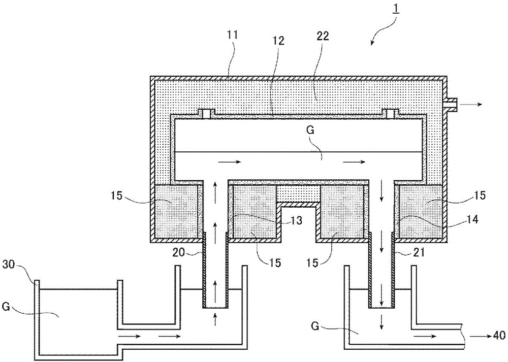
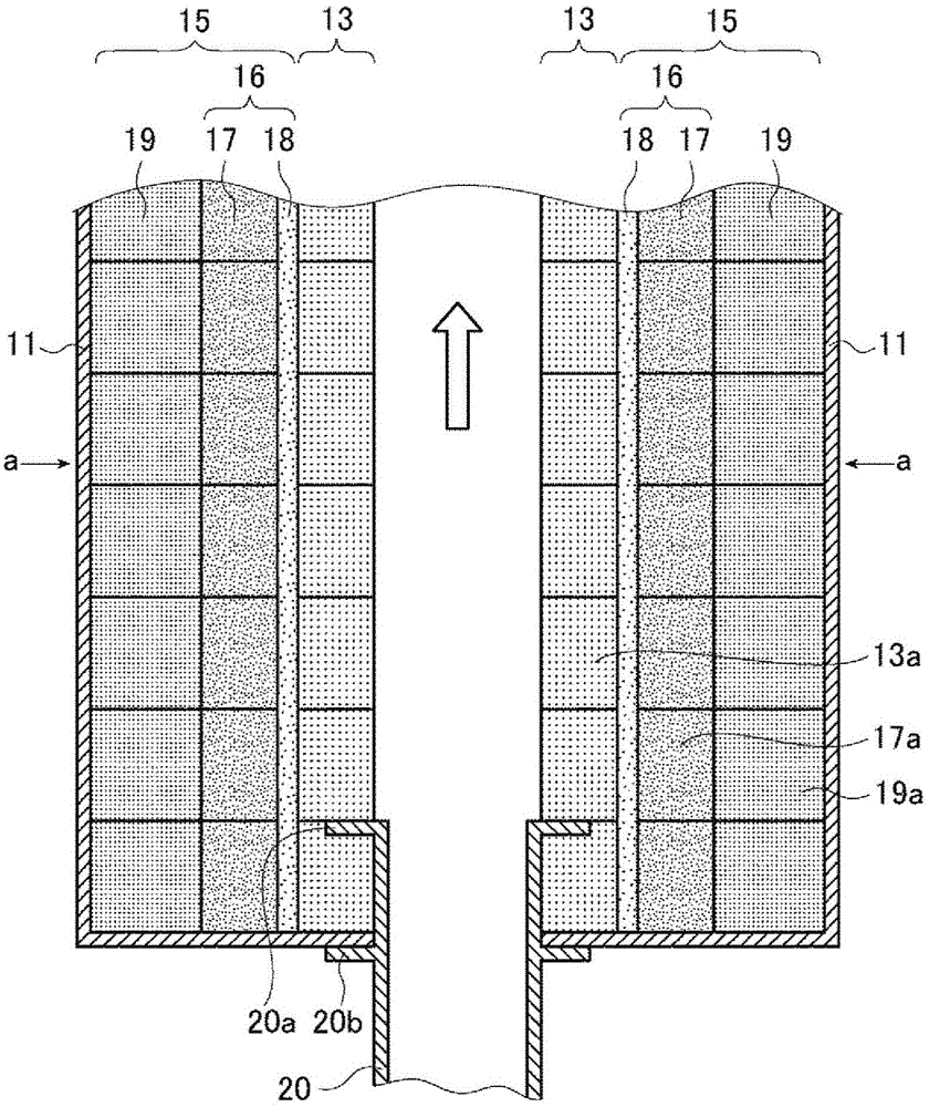
[0179] In this example, use figure 1 The vacuum degassing device 1 shown is used to implement the vacuum degassing of molten glass. In the vacuum degassing device 1, the riser 13, the downcomer 14 and their peripheral positions have figure 2 structure shown.
[0180] The structural materials of each part of the vacuum degassing apparatus 1 are as follows.
[0181] ·Decompression housing 11: stainless steel
[0182] ·Decompression degassing tank 12: electroformed brick
[0183] ·Rising tube 13, down tube 14: electroformed brick
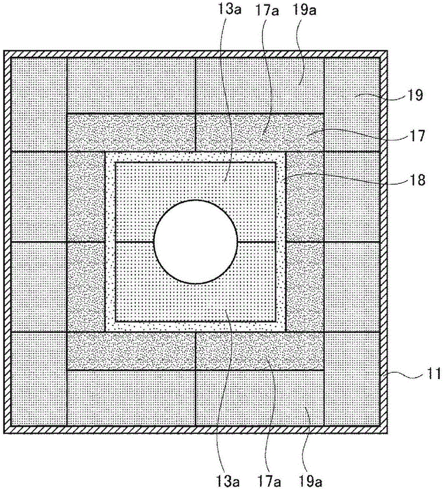
[0184] The riser 13 is constructed by combining two electroformed bricks 13a (alumina electroformed bricks) to form image 3In the shape shown, they are stacked along the long axis direction of the riser pipe 13 . The structure of the downcomer 14 is also the same as that of the riser 13 .
[0185] · Extension tubes 20, 21: Platinum
[0186] Around the ascending pipe 13 and the descending pipe 14, there are figure 2 The support 15 of the str...
PUM
Property
Measurement
Unit
compressive strength
aaaaa
aaaaa
porosity
aaaaa
aaaaa
compressive strength
aaaaa
aaaaa
Abstract
Provided are: a molten glass conduit structure, in which the erosion of a solid heat insulating material constituting a backup of a conduit can be prevented by a molten glass that exudes from a joint part between electrocast bricks constituting the conduit, without using any cooling means, and which can be manufactured at a reduced cost; a vacuum defoaming device using the conduit structure; and a method for vacuum defoaming a molten glass using the vacuum defoaming device. The molten glass conduit structure, said conduit structure comprising a conduit and a backup provided on the periphery of the conduit, is characterized in that: the conduit is a hollow tube having electrocast bricks disposed in the longitudinal direction and circumferential direction thereof; the backup comprises a refractory layer provided on the outside of the conduit and a heat insulating material layer provided on the outside of the refractory layer; the refractory layer comprises a refractory brick layer consisting of refractory bricks disposed in the longitudinal direction and circumferential direction of the conduit and a monothilic refractory layer that is formed by laying a monothilic refractory, said monothilic refractory containing, in terms of mass percentage of oxide(s), 30-100% of Al2O3 and 0-70% of SiO2, and then sintering the monothilic refractory; the heat insulating material layer comprises a solid heat insulating material layer comprising a solid heat insulating material disposed in the longitudinal direction and circumferential direction of the conduit; and the electrocast bricks constituting the conduit, the monothilic refractory constituting the monothilic refractory layer and the refractory bricks constituting the refractory brick layer are selected in such a manner that, when the molten glass passes through the conduit, a site being at the same temperature as the pour point of the glass is positioned within the heat insulating material layer.
Description
technical field [0001] The present invention relates to conduit structures for molten glass. The conduit structure for molten glass of the present invention can be used as a conduit for molten glass in a glass manufacturing apparatus, for example, as a riser, a vacuum degassing tank, or a downcomer of a vacuum degassing apparatus. The conduit structure for molten glass of the present invention is suitably used as a riser, a vacuum degassing tank, or a downcomer of a vacuum degassing device. [0002] In addition, the present invention relates to a conduit for molten glass, especially a riser, a vacuum degassing tank, or a downcomer, a vacuum degassing device using the conduit structure, and a degassing device for molten glass using the vacuum degassing device. Pressure defoaming method. [0003] Moreover, this invention relates to the glass manufacturing method which uses the above-mentioned conduit structure for at least a part of the conduit of molten glass. [0004] Moreo...
Claims
Application Information
Patent Timeline
Application Date:The date an application was filed.
Publication Date:The date a patent or application was officially published.
First Publication Date:The earliest publication date of a patent with the same application number.
Issue Date:Publication date of the patent grant document.
PCT Entry Date:The Entry date of PCT National Phase.
Estimated Expiry Date:The statutory expiry date of a patent right according to the Patent Law, and it is the longest term of protection that the patent right can achieve without the termination of the patent right due to other reasons(Term extension factor has been taken into account ).
Invalid Date:Actual expiry date is based on effective date or publication date of legal transaction data of invalid patent.