
Wireless photoelectric smoke sensing detector

A detector and photoelectric technology, applied in the field of smoke detectors, can solve problems such as poor environmental adaptability, false alarms, high installation and maintenance costs, and achieve the effect of improving accuracy and reducing power consumption

Active Publication Date: 2015-12-02
SHANDONG BEIRENHUIZHI ENERGY DEV
View PDF10 Cites 14 Cited by
  • Summary
  • Abstract
  • Description
  • Claims
  • Application Information

AI Technical Summary

Problems solved by technology

These smoke detectors require a large area of ​​wiring during installation. If a detector fails during use, a large area needs to be checked, and the installation and maintenance costs are relatively high.
[0004] Existing smoke detectors that use wireless transmission, the labyrinth is located on the side of the entire circuit board, if the detector is installed in an unfavorable smoke sensing position, when there are smoke signals from different directions, the sound and light alarm cannot be issued in time
Chinese patent CN03203787.2 discloses a smoke detector, which cannot meet the requirements of the national standard GB20517-2006 on the directionality test
Although the threshold method is simple and easy to implement, it has poor adaptability to the environment and is prone to false positives.
During the installation and use of the detector, the maze of the detector is easily polluted by dust in the environment, and the scattering path of light in the maze changes, resulting in false alarms

Method used


Image

  • Wireless photoelectric smoke sensing detector
  • Wireless photoelectric smoke sensing detector
  • Wireless photoelectric smoke sensing detector

Examples


Embodiment Construction

[0033] Combine below Attached picture The present invention will be further described with specific examples, but they are not used to limit the scope of the present invention.

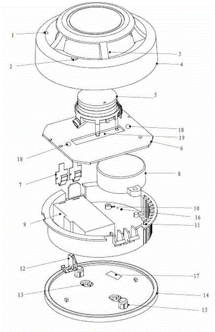
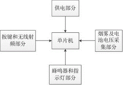
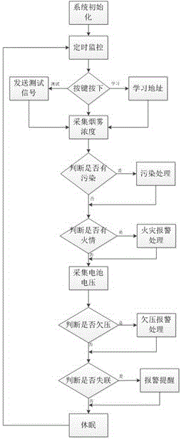
[0034] Such as attached figure 1 As shown, the wireless photoelectric smoke detector of the present invention is sequentially provided with an upper case 4, a circuit board 6, a bottom case 11, and a mounting base 14 from top to bottom, and is characterized in that: the top of the upper case is provided with a button hole 1 And alarm indicator hole 2, the central position of described circuit board 6 has groove 19, and the front of circuit board 6 connects labyrinth 5 by groove 19, and the interface of two infrared pair tubes 18 of labyrinth 5 is 180 °, can It is just stuck in the groove 19 of the circuit board 6, which can ensure that the smoke passes through the maze 5 relatively evenly. The upper cover of the maze 5 is just attached to the inner wall of the upper shell 4, and the maze 5 can be...


PUM


Abstract

The invention relates to a smoke detector, and especially relates to a photoelectric smoke sensing detector by utilization of low-power-consumption wireless communication technology and eliminating environment interference. The wireless communication technology and the smoke sensing detection technology are combined, the smoke sensing detector can detect fire behaviors independently, can is communicated with a fire-fighting host, and has a fire-fighting linkage effect. For processing of a smoke signal, an environment base value following pollution processing method is employed, and a false alarm or the like caused by environment interference in a labyrinth is eliminated in time. Housing design employs an electrode contact mode, unnecessary troubles caused by detector removal for man-made reasons during the usage process of the detector can be detected well, a 433MHz wireless communication technology is employed, a wireless radio frequency processing chip with a response mode is employed, bidirectional intercommunication of information can be achieved, and the system power consumption is reduced. A 9V lithium battery is employed, the situation is ensured that the detector can work normally for 6-8 years under a condition that the cell supplies power, and a trouble of replacing a cell is avoided for a user.

Description

technical field [0001] The invention relates to a smoke detector, in particular to a photoelectric smoke detector which utilizes low-power consumption wireless communication technology and simultaneously eliminates environmental interference. Background technique [0002] Existing smoke detectors are the most widely used and the most numerous detectors in the world. It is widely used in homes, shopping malls, hotels, office buildings, dance halls, warehouses and other places. Smoke detectors are divided into point and line smoke detectors. Among them, point-type smoke detectors are widely used in the market, and point-type detectors are divided into ion-type and photoelectric smoke detectors. [0003] Most of the existing photoelectric smoke detectors are wired fire protection products, and most of them are independent detectors. These smoke detectors require a large area of ​​wiring during the installation process. If a detector fails during use, a large area of ​​invest...

Claims


Application Information

Patent Timeline
IPC IPC(8): G08B17/12
CPCG08B17/12
Inventor 刘燕燕王新李洪刚马志国范新虎杨国强
Owner SHANDONG BEIRENHUIZHI ENERGY DEV
Learn More