Image sensor, imaging device, endoscope, endoscope system and driving method of image sensor

A technology for imaging elements and endoscopes, applied in the field of imaging elements, can solve problems such as image distortion

Active Publication Date: 2015-11-25
OLYMPUS CORP
View PDF6 Cites 4 Cited by
  • Summary
  • Abstract
  • Description
  • Claims
  • Application Information

AI Technical Summary

Problems solved by technology

Therefore, at the beginning of the imaging signal period, fluctuations in power supply voltage occur due to fluctuations in power consumption, resulting in image distortion.

Method used


Image

  • Image sensor, imaging device, endoscope, endoscope system and driving method of image sensor
  • Image sensor, imaging device, endoscope, endoscope system and driving method of image sensor
  • Image sensor, imaging device, endoscope, endoscope system and driving method of image sensor

Examples


Embodiment approach

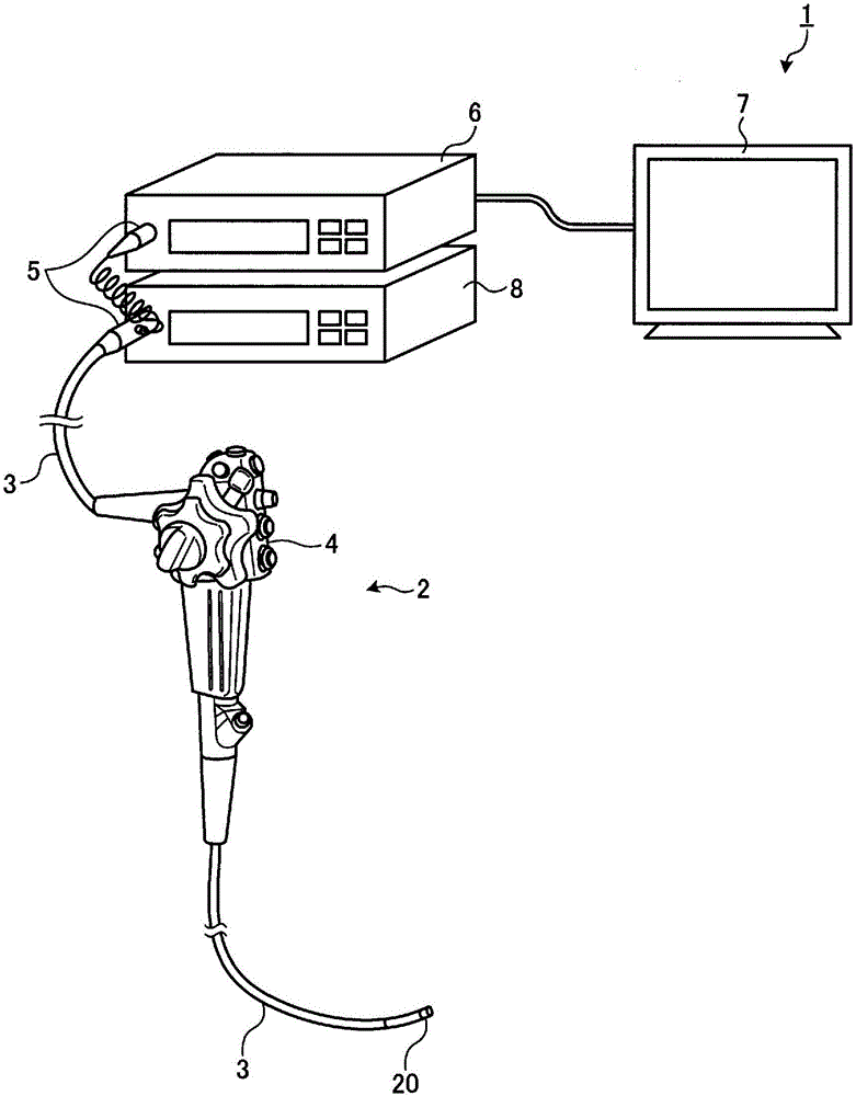
[0030] figure 1 It is a diagram schematically showing the overall configuration of the endoscope system according to Embodiment 1 of the present invention. An endoscope system 1 shown in the figure includes an endoscope 2 , a transmission cable 3 , a connector unit 5 , a processor (control device) 6 , a display device 7 , and a light source device 8 . The endoscope 2 captures in-vivo images of the subject and outputs imaging signals by inserting an insertion portion that is a part of the transmission cable 3 into the body cavity of the subject. The transmission cable 3 connects the endoscope 2 and the connector unit 5 . The connector unit 5 is connected to the endoscope 2, the processor 6, and the light source device 8, performs predetermined signal processing on the imaging signal output from the connected endoscope 2, and performs analog / digital conversion (A / D) on the imaging signal. D conversion) and output it as an image signal. The processor 6 performs predetermined ...


PUM


Abstract

An image sensor comprises: multiple pixels that are arranged in a two-dimensional matrix, receive light from outside, and generate and output an imaging signal corresponding to the amount of received light; a reference voltage generation unit which generates a reference voltage; and a phase adjustment signal generation unit which outputs a phase adjustment signal to be used for phase adjustment in response to the reference voltage when the pixels are not outputting an imaging signal.

Description

technical field [0001] The present invention relates to an imaging element, an imaging device, an endoscope, an endoscope system, and a driving method of the imaging element. Background technique [0002] In an imaging device having a CMOS (Complementary Metal-Oxide Semiconductor: Complementary Metal-Oxide Semiconductor) imaging element, power consumption differs between a blanking period and an imaging signal period. Therefore, at the beginning of the imaging signal period, fluctuations in power supply voltage occur due to fluctuations in power consumption, and image distortion occurs. [0003] In order to suppress such fluctuations in power consumption, there has been proposed a method of providing a circuit for passing a current while power consumption is falling (for example, refer to Patent Document 1). In the technology described in Patent Document 1, during the blanking period when the load current of the horizontal transfer circuit falls below a predetermined thresh...

Claims


Application Information

Patent Timeline
Patent Type & Authority Applications(China)
IPC IPC(8): A61B1/04G02B23/24H04N7/18
CPCG02B23/2476A61B1/00006A61B1/045A61B1/05H04N5/361H04N5/378H04N7/183H04N23/555H04N25/63H04N25/65H04N25/709H04N25/75A61B1/000095H04N23/54H04N25/71
Inventor 赤羽奈奈小野诚西胁隆浩细贝克己
Owner OLYMPUS CORP
Why Eureka
Try Eureka