
Oil slurry filtration system

A filtration system and oil slurry technology, applied in the direction of filtration and separation, refining by filtration, fixed filter element, etc., can solve the problems of complicated control, prolonged time, shortened system operation period, etc., to achieve stable system operation and maintain stability The effect of sex, operation simplification

Inactive Publication Date: 2015-11-25
张雷
View PDF3 Cites 3 Cited by
  • Summary
  • Abstract
  • Description
  • Claims
  • Application Information

AI Technical Summary

Problems solved by technology

Because when one filter is backwashing, there is only one filter running online, and when the filter is backwashed and on-line, the filter becomes two working at the same time. This change makes the system unstable and the control is complicated. The failure rate is high, and it is difficult for the operator to master the operation of the system
In addition, because the system does not have a soaking process in the normal working process, it cannot effectively remove the colloid and asphaltene attached to the filter screen, which greatly shortens the system operating cycle
Moreover, when the system is backwashing, the pressure of the filter and the pressure of the filter cake receiving tank need to be changed, which will prolong the time of the process. Since the process is a process of changing the set value, the control is more complicated. The stability of the control is not ideal
Therefore, the current situation of the filter system of this working mode is not very ideal in field application

Method used


Image

  • Oil slurry filtration system
  • Oil slurry filtration system
  • Oil slurry filtration system

Examples


Embodiment 1

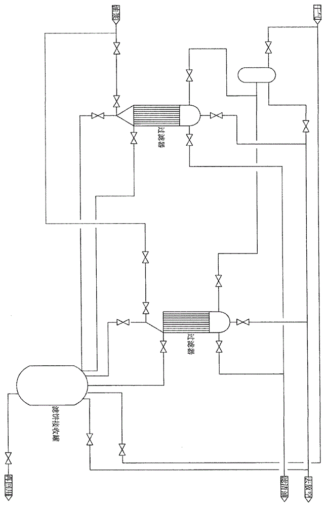
[0056] Such as Figure 5 As shown, the oil slurry filtration system of the present invention includes: three filters 1, soaking liquid buffer tank 2, discharge buffer tank 3 and filter cake receiving buffer tank 4;

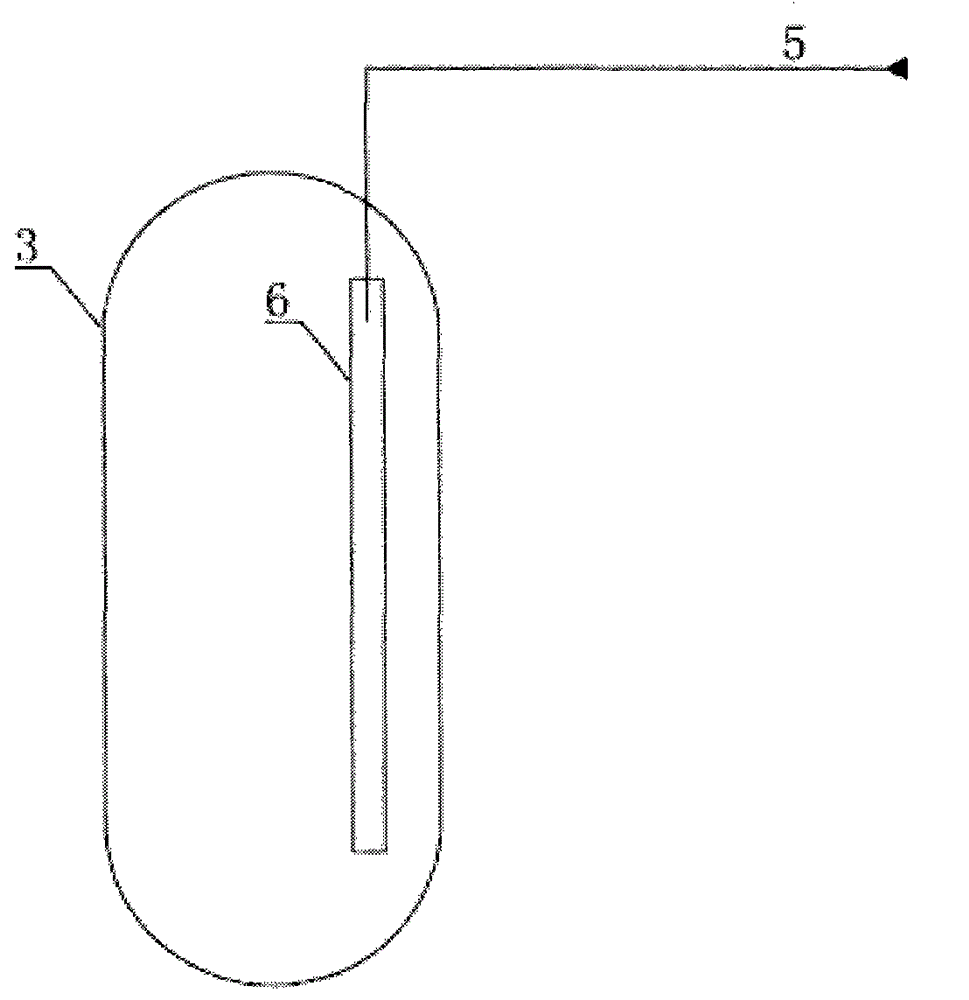
[0057] Wherein, the three filters 1 are respectively provided with oil slurry inlet pipelines, so that the oil slurry can enter the three filters respectively, and the tops of the three filters 1 are respectively provided with pipelines directly connected to the discharge pipes. The pipeline connected to the buffer tank, so that the discharge filtered by the three filters can enter the discharge buffer tank 3;

[0058] The discharge buffer tank 3 is used to receive the discharge filtered by the three filters;

[0059] The soaking liquid buffer tank 2 is provided with a pipeline directly connected to the three filters, so that the filter not in the filtering state is soaked, and the soaking liquid buffer tank is also provided with a pipe connected to the discharge...


PUM


Abstract

The invention relates to an oil slurry filtration system. The filtration system comprises: three filters, an immersion liquid buffer tank, a discharging buffer tank and a filter cake receiving buffer tank; wherein the three filters are respectively provided with oil slurry entering pipelines, so that oil slurry can respectively enter into the three filters, and the tops of the three filters are also respectively provided with pipelines which are directly connected with the discharging buffer tank, so that discharging filtered from the three filters can enter into the discharging buffer tank; the discharging buffer tank is used for receiving the discharging filtered by the three filters; the immersion liquid buffer tank is provided with pipelines which are directly connected with the three filters, so that the filter which is not in the filtering state can be immersed; the filter cake receiving buffer tank is provided with pipelines which are directly connected with the three filters, so that residues filtered by the three filters can be received. The system provided by the invention has the advantages of simple operation and stable system.

Description

technical field [0001] The invention relates to a solid-liquid separation device, in particular to a novel oil slurry filtration system. Background technique [0002] The external oil slurry of the catalytic cracking unit is discharged in the form of external dumping of the tailings that cannot be cracked during the production process of the catalytic cracking unit of the refinery. Since the catalytic cracking unit adopts fluidized bed reaction, solidified catalyst powder is inevitably contained in the external oil slurry, and the solid content is 3000-20000ppm. Therefore, it is necessary to filter out the solid particles by means of filtration. And in order to improve work efficiency, it is also necessary to use a continuous filtration filtration system for work. The oil slurry filtration system is a continuous operation solid-liquid separation device that can filter the solids in the oil slurry. [0003] Currently commonly used slurry filtration systems such as figure ...

Claims


Application Information

Patent Timeline
Patent Type & Authority Applications(China)
IPC IPC(8): C10G31/09B01D29/50B01D29/52B01D29/62B01D29/66
Inventor 张雷张轶轩
Owner 张雷
Learn More