
Water-jet machining device

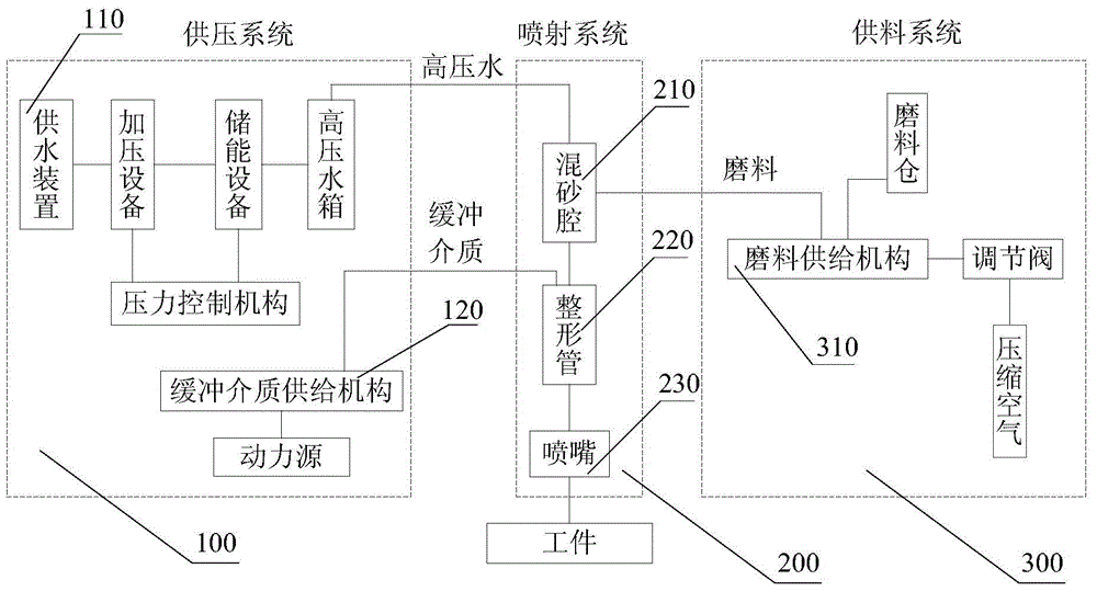
A processing device and water jet technology, which is applied in metal processing equipment, used abrasive processing devices, manufacturing tools, etc., can solve the problem of high wear rate of nozzles and sand mixing chambers, wear of sand mixing chambers and nozzles, and affecting processing capacity. and other problems to achieve consistent control, reduce maintenance costs, and control wear and tear.

Inactive Publication Date: 2015-11-25
NINGBO INST OF MATERIALS TECH & ENG CHINESE ACADEMY OF SCI
View PDF6 Cites 4 Cited by
  • Summary
  • Abstract
  • Description
  • Claims
  • Application Information

AI Technical Summary

Problems solved by technology

[0003] The nozzle and sand mixing chamber of general water jet processing devices have a high wear rate. The main reason for the high wear rate is that when the water jet mixed with abrasive passes through the nozzle and the sand mixing chamber under high pressure and high speed, the abrasive will directly rub against the nozzle. And the inner wall of the sand mixing chamber, which will cause the wear of the sand mixing chamber and the nozzle, and finally affect the processing capacity
This requires frequent replacement of the sand mixing chamber and nozzles, resulting in high maintenance costs

Method used


Image

  • Water-jet machining device
  • Water-jet machining device
  • Water-jet machining device

Examples


Embodiment 1

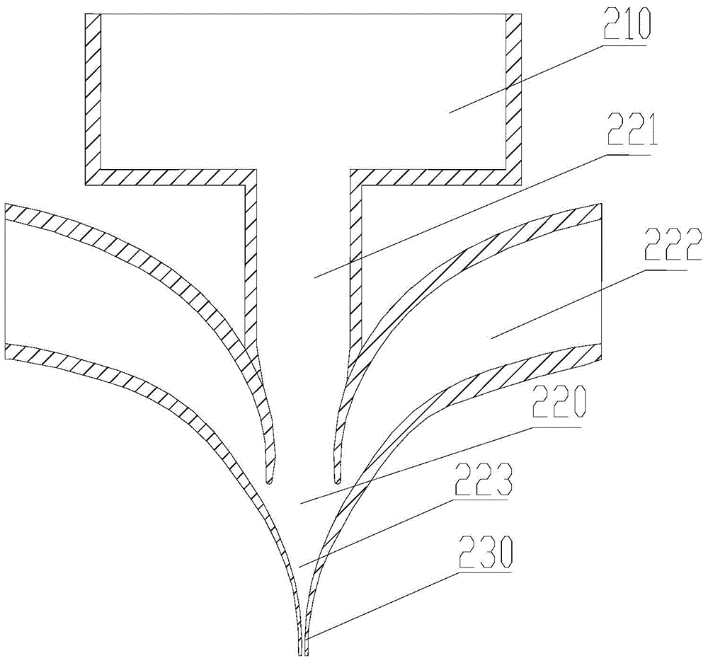
[0050] like figure 2 As shown, the inner wall of the outlet 223 of the shaping tube is a smooth inner wall, and the length of the nozzle 230 is relatively short. In the sand mixing chamber 210, the mixed liquid after mixing the abrasive and high-pressure water is sprayed out through the outlet of the sand mixing chamber 210 to form a central water jet. The flow velocity of the mixed liquid in the sand mixing chamber 210 is relatively low, and the flow velocity of the mixed liquid in the sand mixing chamber 210 is much lower than that of the central water jet. The flow velocity of the mixed liquid in the traditional high-pressure sand mixing chamber is greater than 400 m / s, but in this embodiment, the flow velocity of the mixed liquid in the sand mixing chamber 210 is lower than 20 m / s. In this way, the wear of the abrasive on the inner wall of the sand mixing chamber 210 is much smaller than that of a traditional high-pressure sand mixing chamber, reducing the wear rate of t...

Embodiment 2

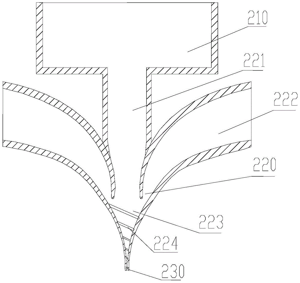
[0054] like image 3 As shown, in order to further enhance the wrapping degree of the buffer medium on the central water jet, the inner wall of the outlet 223 of the shaping tube can be designed as a non-smooth inner wall with a geometric structure. Preferably, the inner wall of the outlet 223 of the shaping tube is provided with a helical slot 224, so that the buffer medium produces a helical effect before merging with the central water jet, so as to improve the stability of the package. According to the simulation results of the experiment, it can be seen that the shaping tube 220 with the helical slot 224 can better maintain the stability of the central water jet and improve the kinetic energy of the central water jet than the smooth shaping tube 220 .

Embodiment 3

[0056] like Figure 4 As shown, in this embodiment, the nozzle 230 is a linear narrow structure, and by controlling the outer diameter of the nozzle 230, the nozzle 230 can go deep into a narrow space for processing. Preferably, the outer diameter of the nozzle 230 is less than 3 mm, the inner diameter is less than 50 microns, and the length of the nozzle 230 is greater than 100 mm. In the conventional technology, since the abrasive directly contacts the inner wall of the nozzle 230 , the wear of the abrasive on the nozzle 230 will greatly reduce the service life of the nozzle 230 , so the length of the nozzle 230 is relatively short. In this embodiment, the length of the nozzle 230 can be designed longer and the diameter of the nozzle 230 can be designed smaller because the buffer medium reduces the wear rate of the nozzle 230 . In this embodiment, the material of the nozzle 230 is tungsten carbide, and the hole shape of the nozzle 230 is circular. Certainly, the material o...


PUM


Abstract

Provided is a water jet machining device, comprising a pressure provision system, a jet system, and a feed provision system. The pressure provision system and the feed provision system are separately connected to the jet system. The jet system comprises a sand-mixing chamber and a nozzle. High-pressure water and an abrasive are mixed to form a mixture in the sand-mixing chamber. The jet system also comprises a shaping tube. A first inlet of the shaping tube is in communication with the exit of the sand-mixing chamber. The exit of the shaping tube is in communication with the nozzle. The mixture is injected into the shaping tube from the exit of the sand-mixing chamber at a low speed, forming a central water jet. The pressure provision system also comprises a buffering medium provision mechanism. The buffering medium provision mechanism is in communication with a second inlet of the shaping tube. The buffering medium provision mechanism injects the buffering medium into the shaping tube. The buffering medium sleeves the central water jet. The central water jet sleeved in the buffering medium is ejected out of the nozzle and works on the component to be machined. The water jet machining device of the present invention lowers the wear rate of the nozzle and the sand-mixing chamber, thereby reducing maintenance costs.

Description

technical field [0001] The invention relates to the technical field of water jet processing, in particular to a water jet processing device. Background technique [0002] Water jet processing includes pure water water jet processing and abrasive water jet processing with additional abrasives. The wear of the nozzle by pure water jet processing is much lower than that of abrasive water jet processing, but the processing efficiency of pure water jet processing is much lower than that of abrasive water jet processing. [0003] The nozzle and sand mixing chamber of general water jet processing devices have a high wear rate. The main reason for the high wear rate is that when the water jet mixed with abrasive passes through the nozzle and the sand mixing chamber under high pressure and high speed, the abrasive will directly rub against the nozzle. And the inner wall of the sand mixing chamber, which will cause the wear of the sand mixing chamber and the nozzle, and finally affec...

Claims


Application Information

Patent Timeline
Patent Type & Authority Applications(China)
IPC IPC(8): B24C3/02B24C9/00B24C5/00
Inventor 张文武郭春海张天润
Owner NINGBO INST OF MATERIALS TECH & ENG CHINESE ACADEMY OF SCI
Learn More