
Low phase noise wideband microwave local oscillator source circuit and realization method thereof

An implementation method and wide-band technology, which are applied in the low-phase noise wide-band microwave local oscillator source circuit and the low-phase noise wide-band microwave local oscillator source realization field, can solve the problem of wide frequency range, narrow output frequency range, multiple spurious Signal and other problems, to achieve the effect of wide output frequency range, compact circuit structure and high degree of integration

Active Publication Date: 2015-11-18
THE 41ST INST OF CHINA ELECTRONICS TECH GRP
View PDF4 Cites 14 Cited by
  • Summary
  • Abstract
  • Description
  • Claims
  • Application Information

AI Technical Summary

Problems solved by technology

[0007] In the existing broadband phase-locked loop circuit, most commonly used phase-locked loop solutions are built with integrated phase-locked loop chips and dedicated VCOs, which have the characteristics of simple circuit structure and low power consumption. However, due to the high frequency band and wide frequency range, Phase noise can not achieve good results
[0008] The commonly used phase-locked loop frequency synthesis technology uses the signal after the frequency division of the output signal as the feedback signal, and mixes it with the reference signal. The mixed signal is used as the input phase detection signal of the phase detector, and the phase noise index of the signal is poor. , the output frequency range is narrow
[0009] Direct digital frequency synthesis technology is limited by the highest available clock frequency of the device. The upper limit of the output frequency is not high enough to produce the output signal frequency of the radio frequency band. The use of the DAC device that is indispensable in this technology makes its output signal produce a comparison Many spurious signals affect the signal quality

Method used


Image

  • Low phase noise wideband microwave local oscillator source circuit and realization method thereof

Examples


Embodiment Construction

[0046] The following will clearly and completely describe the technical solutions in the embodiments of the present invention with reference to the accompanying drawings in the embodiments of the present invention. Obviously, the described embodiments are only some, not all, embodiments of the present invention. Based on the embodiments of the present invention, all other embodiments obtained by persons of ordinary skill in the art without making creative efforts belong to the protection scope of the present invention.

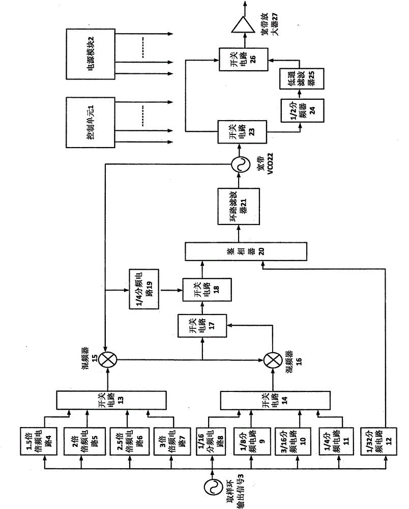
[0047]In the existing frequency synthesis technology, the designed broadband local oscillator circuit needs to have the characteristics of high frequency band, wide frequency range, and low phase noise, and most of them use multiple phase-locked loops to work together to ensure that the phase noise of the output signal can meet the requirements of the whole machine. indicator requirements. Since the output frequency range is wide and it works in the microwave ...


PUM


Abstract

The present invention provides a low phase noise wideband microwave local oscillator source circuit which is formed by two phase-locked loops. The frequency division signal of a broadband voltage-controlled oscillator directly enters a phase detector to form phase-locked loops with a reference signal, and the preset of the whole loop is realized. Then through switch switching, the output signal of the voltage-controlled oscillator and the frequency doubling and frequency division of a sampling ring output signal are mixed, the phase locking is carried out again, and the function of a low noise is realized. According to the low phase noise wideband microwave local oscillator source circuit, a wideband VCO chip is used, the outputted frequency range is 3GHz to 10GHz, and the phase noise of a 10GHz signal can reach -120dBc / Hz@10kHz. According to the low phase noise wideband microwave local oscillator source circuit, while very low phase noise is obtained, the number of used devices is greatly reduced, a PCB space is saved, the volume is only 16cm by 9cm by 2cm, the debugging difficulty is reduced, and the power consumption is reduced.

Description

technical field [0001] The invention relates to the technical field of frequency synthesis, in particular to a low-phase-noise wide-band microwave local oscillator circuit and a method for realizing a low-phase-noise wide-band microwave local oscillator. Background technique [0002] Frequency synthesizers are widely used, such as in radar, communication, navigation and other fields, and are an important part of modern electronic systems. With the continuous development of electronic technology, various electronic systems have higher and higher requirements for the performance indicators of frequency synthesizers, such as frequency conversion time, phase noise, spurious, frequency range and other indicators. . Among them, phase noise is a key factor that determines the performance of the frequency synthesizer. Low phase noise performance can improve the improvement factor of the radar and improve the ability to detect signals in a strong background environment of the radar;...

Claims


Application Information

Patent Timeline
Patent Type & Authority Applications(China)
IPC IPC(8): H03L7/18H03L7/099
Inventor 杨宜生黄珍元李维亮王李飞
Owner THE 41ST INST OF CHINA ELECTRONICS TECH GRP
Learn More