
A flat-panel bone conduction earphone with adjustable receiving position

A bone conduction earphone and tablet technology, which is applied in the field of tablet bone conduction earphones, can solve the problems of limited high frequency vibration frequency, inability to hang the earphone bracket comfortably and tightly, and insufficient bass performance.

Active Publication Date: 2022-03-22
HEAD DIRECT KUNSHAN CO LTD
View PDF8 Cites 0 Cited by
  • Summary
  • Abstract
  • Description
  • Claims
  • Application Information

AI Technical Summary

Problems solved by technology

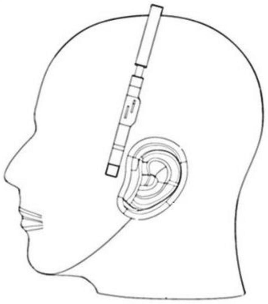
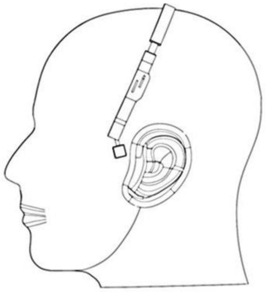
[0004] The sound transmission effect of bone conduction earphones depends on the good close fit between the sound unit and the user's head. However, the existing bone conduction earphones are limited to the ear-mounted wearing method, and the interaction position between the sound unit and the user cannot be adjusted. , so that the fit between the sound unit and the user's head is limited. For example, a user wearing glasses cannot comfortably and tightly hang the earphone holder due to the restriction of the glasses holder, and a user with thick sideburns cannot because of the restriction of hair. Ensure a good and tight fit between the sounding unit and the head. Users who wear accessories on the head need to change the position where the sounding unit fits the face due to the limitation of the jewelry
That is, the existing bone conduction earphones cannot change the wearing posture of the earphones and the interaction position between the sound unit and the user, thereby reducing the user's wearing and listening experience of the bone conduction earphones
[0005] In addition, the existing bone conduction earphones are based on the dynamic speaker structure, and the movement of the energized coil in the magnetic field directly drives the external structure to apply vibration to the user's skull, which is limited by the power output capability of the dynamic coil and the input of the human bone to the vibration excitation. Requirements, its high-frequency vibration frequency is limited, and the subwoofer performance is insufficient

Method used


Image

  • A flat-panel bone conduction earphone with adjustable receiving position
  • A flat-panel bone conduction earphone with adjustable receiving position
  • A flat-panel bone conduction earphone with adjustable receiving position

Examples


Embodiment 1

[0046] see figure 1 , figure 1 It is a perspective view of a bone conduction earphone according to an embodiment of the present invention. This embodiment provides a flat-plate bone conduction earphone with adjustable sound receiving position, which includes a main bracket 1, two angle adjustment structures 2 and two sounding units 3, the main bracket 1 is U-shaped, and the two sounding units 3 are respectively connected to the U-shaped ends of the main bracket 1 through the two angle adjustment structures 2;

[0047] The main bracket 1 includes a sliding groove 11 and a turning groove 12, and the sliding groove 11 and the turning groove 12 are arranged at both ends of the U shape of the main bracket 1 in a cross shape along the axial direction of the main bracket 1;

[0048] The angle adjustment structure 2 includes a connecting piece 22 and an elastic bracket 21;

[0049] The connecting piece 22 is arranged in the chute 11, the elastic bracket 21 is movably connected to t...

Embodiment 2

[0064] like Figure 8 and Figure 9 As shown, among them, Figure 8 It is an exploded view of the bone conduction earphone plate type vibration unit according to the embodiment of the present invention, Figure 9 It is an axial sectional view of the plate vibration unit of the bone conduction earphone according to the embodiment of the present invention. The sound unit 3 provided in this embodiment includes a flat vibration unit 32, and the flat vibration unit 32 includes a housing 321, a stator bracket, a magnetic pole 322, a diaphragm bracket, a diaphragm 325, a coil 3251, a vibration support frame 328, and a rear cover 330 and vibrating piece 329, the magnetic pole 322 is at least one cylindrical magnet, and the cylindrical magnet has at least one planar outer surface, and the planar outer surface is set toward the vibrating membrane 325, and the vibrating piece 329 is used to place the The vibration of the diaphragm 325 is transmitted to the skull of the user.

[0065]...

Embodiment 3

[0073] like figure 1 , Figure 6 As shown, among them, figure 1 It is a perspective view of a bone conduction earphone according to an embodiment of the present invention, Figure 6 It is a partial schematic diagram of the functional unit of the bone conduction earphone according to the embodiment of the present invention. In this embodiment, the U-shaped sides of the main bracket 1 are provided with functional units 4, and the functional units 4 include a wireless transmission unit, a power supply unit, a power amplifier unit, a control unit, a touch key unit 41, and an attitude sensing unit 42 and a storage unit; the posture sensing unit 42 includes a gravity sensing sensor.

[0074] The touch key unit 41 is arranged outside the functional unit 4 in a depressible manner, and the touch key unit 41 has a touch sensing function.

[0075] The posture sensing unit 42 is used to judge the posture of the bone conduction earphone; the control unit is connected with the posture s...


PUM


Abstract

The invention relates to a flat-plate bone conduction earphone with an adjustable sound-receiving part, which includes a main bracket, two angle adjustment structures and two sounding units based on a flat-plate vibration unit, wherein the sounding unit is connected to the main bracket through the angle adjustment structure, The cross-shaped chute on the main bracket, the connecting piece in the rotating groove and the angle adjustment structure, and the elastic bracket realize the diverse adjustment of the position of the sound unit. Fit the position to avoid head hair, ornaments or glasses brackets from interfering with the wearing and sound collection of bone conduction headphones, and improve the listening effect of bone conduction headphones.

Description

technical field [0001] The invention relates to the field of bone conduction earphones, in particular to a plate-type bone conduction earphone with an adjustable sound receiving part. Background technique [0002] Bone conduction is a way for people to receive sound signals. Sound transmits and receives sound signals through the human skull, bone labyrinth, inner ear lymph, screw, auditory nerve, and auditory center. The ear method saves the transmission of sound in the air, so that the sound signal can be clearly restored in a noisy background environment. [0003] Bone conduction earphones are earphones designed and manufactured using bone conduction technology. They are often used in the field of hearing aids, sports earphones, and special earphones for military and police due to their special sound conduction and usage methods. They have the advantages of less distortion, liberating both ears, and easy wearing. . [0004] The sound transmission effect of bone conductio...

Claims


Application Information

Patent Timeline
Patent Type & Authority Patents(China)
IPC IPC(8): H04R1/10H04R9/02H04R9/06
CPCH04R1/10H04R9/06H04R9/02H04R9/025H04R2460/13
Inventor 边仿
Owner HEAD DIRECT KUNSHAN CO LTD
Learn More