
Compact cylindrical ion exchange membrane fuel cell and preparation method thereof

An ion exchange membrane and fuel cell technology, which is applied in the field of compact cylindrical ion exchange membrane fuel cells, can solve the problems of high production cost and large volume of bipolar plates, and achieves compact structure, small overall structure and volume, and damage resistance. Good results

Active Publication Date: 2015-11-18
XI AN JIAOTONG UNIV
View PDF5 Cites 13 Cited by
  • Summary
  • Abstract
  • Description
  • Claims
  • Application Information

AI Technical Summary

Benefits of technology

This new design improves the efficiency and effectiveness of solid oxide type (SOFCs), specifically ceramics that generate electric power from hydrocarbon fuels such as gasoline or diesel oil. These SOC's have several advantages over existing technologies like coal fired boilers for generating energy due to their high thermal stability compared to other methods. They also offer improved control capabilities during operation because they operate under specific conditions depending upon factors like temperature and humidity levels. Overall these improvements enhance the functionality and durability of SOFC systems while reducing manufacturing costs.

Problems solved by technology

The technical problem addressed in this patented text relating to traditional batteries used for generating electricity by converting chemicals into electrical current through electrochemistry involves having issues with size, weightiness, costs associated with producing these materials, and potential health hazards caused during production processes due to harmful substances released when they are produced.

Method used


Image

  • Compact cylindrical ion exchange membrane fuel cell and preparation method thereof
  • Compact cylindrical ion exchange membrane fuel cell and preparation method thereof
  • Compact cylindrical ion exchange membrane fuel cell and preparation method thereof

Examples


Embodiment 1

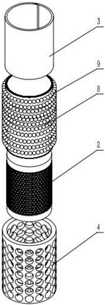
[0051] Such as figure 1 As shown, a compact cylindrical ion-exchange membrane fuel cell 1 sequentially includes a compact pole-membrane integrated fuel chamber 2 , a cathode hydrophobic diffusion layer 3 and a cylindrical sealed collector cover 4 .

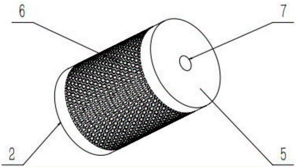
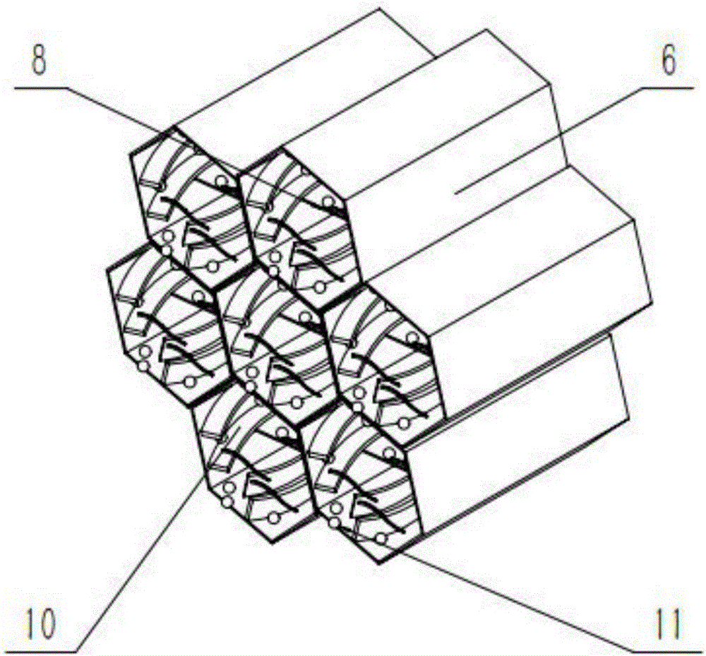
[0052] Such as figure 2 As shown, the compact pole-membrane integrated fuel cavity 2 includes a cylindrical fuel cavity 5, a honeycomb porous structure 6, and a fuel filling hole 7 at the top. Among them such as image 3 As shown, the honeycomb porous structure 6 further includes secondary channels 10 , an anode catalyst layer 11 and an ion exchange membrane 8 attached to the honeycomb porous structure 6 . The fuel filling hole 7 at the top is used for instant filling of liquid fuel to ensure quick start. The honeycomb porous structure 6 has a plurality of secondary channels 10 in the honeycomb holes. The more compact the honeycomb porous structure, the larger the catalytic active surface area, the smaller the mass transfer re...

Embodiment 2

[0058] In embodiment 2, the difference from embodiment 1 is that the cylindrical sealing header 4 is a complete cylindrical cylindrical structure made of memory alloy material, and there are enough circular air holes 12 to make the The air can fully contact the cathode. When assembling, first expand the radius of the memory alloy cylinder sealing collector 4 at low temperature, so that its diameter is slightly larger than the compact polar membrane integrated fuel chamber wrapped with the cathode hydrophobic diffusion layer 3 2. Then put the cylindrical sealed collecting cover 4 on the compact polar membrane integrated fuel chamber 2 wrapped with the cathode hydrophobic diffusion layer 3 at room temperature, and wait for its radius to return to the original radius to achieve interference Cooperate, provide enough external force to make the cathode hydrophobic diffusion layer 3 close to the compact polar membrane integrated fuel cavity 2, such as Figure 7 As shown, the fabrica...


PUM


Abstract

The invention discloses a compact cylindrical ion exchange membrane fuel cell and a preparation method thereof, belonging to the field of a fuel cell. The preparation method comprises design and fabrication of a compact integrated electrode-membrane fuel cavity, design and fabrication of a cathode hydrophobic diffusion layer and design and fabrication of a cylinder sealing fixing cover. A fuel cavity, an anode diffusion layer, an ion exchange membrane and a cathode catalytic layer are integrated by the compact integrated electrode-membrane fuel cavity, round air vent holes are formed in a cylindrical sealing collection cover, and the cylindrical sealing collection cover is fabricated by applying a three-dimensional (3D) printing rapid proto-typing technology or is made of a memorable alloy material. The compact cylindrical ion exchange membrane fuel cell is compact in structure and is easy to process; compared with the traditional fuel cell, the compact cylindrical ion exchange membrane fuel cell has the advantages of large catalytic activity surface area, low mass transfer resistance and high discharging current, and an electric pile can be assembled according to demands so as to provide required current, voltage and power.

Description


Claims


Application Information

Patent Timeline
Owner XI AN JIAOTONG UNIV
Learn More