
A double-split photovoltaic variable structure

A variable structure, double-split technology, applied in the field of transformers, can solve the problems of increasing difficulty, low copper filling rate, and large number of segments

Active Publication Date: 2017-05-10
NINGBO AUX HIGH TECH
View PDF9 Cites 0 Cited by
  • Summary
  • Abstract
  • Description
  • Claims
  • Application Information

AI Technical Summary

Problems solved by technology

[0003] There are some deficiencies in the existing double-split photovoltaic transformers: the current photovoltaic transformer structure in the industry is a double-split photovoltaic transformer structure, which includes two sets of axially split low-voltage coils, and two sets of axially split and low-voltage coils one by one. Corresponding high-voltage coils and iron cores, two sets of high-voltage coils are arranged axially. When pouring, two sets of high-voltage coils are poured into one coil. Electrically, the two sets of coils are connected in parallel and then lead out uniformly. This structure is used in conventional 10KV products. , due to the low voltage level, the two sets of high-voltage coils are generally wound in four sections, which can meet the performance requirements. A high-voltage coil must have 10 to 12 or more segments, but due to the limited height of the high-voltage coil body, the height of each segment of the coil is limited, which greatly increases the difficulty of winding and may make the coil. The end falls off, resulting in dropped wires and potential safety hazards of short circuit. In addition, because the coils with the same number of segments need to be wound on the two sets of high-voltage coil bodies respectively, the number of segments is large, which makes the filling rate of copper low, thereby increasing the photovoltaic power generation capacity. production cost

Method used


Image

  • A double-split photovoltaic variable structure
  • A double-split photovoltaic variable structure

Examples


Embodiment Construction

[0025] The present invention will be further described below in conjunction with the accompanying drawings.

[0026] In the description of the present invention, it should be understood that the terms "upper", "lower", "inner", "outer", etc. indicating orientation or positional relationship are based on the positional relationship described in the drawings, and are only for the convenience of describing the present invention Or simplify the description instead of indicating a specific orientation that must have.

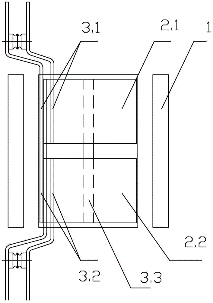
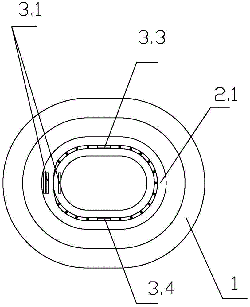
[0027] like figure 1 , figure 2 As shown, a double-split photovoltaic structure is characterized in that it includes a cylindrical high-voltage coil 1, a first low-voltage coil 2.1 and a second low-voltage coil 2.2 located in the high-voltage coil 1, and the first low-voltage coil 2.1 It is axially arranged with the second low-voltage coil 2.2 and there is a gap between the first low-voltage coil 2.1 and the second low-voltage coil 2.2 in the axial direction. The ...


PUM


Abstract

A double-splitting photovoltaic variable structure comprises a barrel-shaped high-voltage coil (1) and a first low-voltage coil (2.1) and a second low-voltage coil (2.2) which are located in the high-voltage coil (1), the first low-voltage coil (2.1) and the second low-voltage coil (2.2) are axially arranged, a gap is formed between the first low-voltage coil (2.1) and the second low-voltage coil (2.2) in the axial direction, the first low-voltage coil (2.1) is provided with a first conductive copper bar (3.1), and the second low-voltage coil (2.2) is provided with a second conductive copper bar (3.2); the double-splitting photovoltaic variable structure further comprises a first transposition copper bar (3.3) and a second transposition copper bar (3.4) which are internally embedded in the low-voltage coils, and the two ends of the first transposition copper bar (3.3) and the two ends of the second transposition copper bar (3.4) are welded to the first low-voltage coil (2.1) and the second low-voltage coil (2.2) respectively.

Description

technical field [0001] The invention relates to the field of transformers, in particular to a double-split photovoltaic transformer structure. Background technique [0002] With the reduction of global energy reserves and the enhancement of human awareness of environmental protection, the scale of the photovoltaic power generation industry is gradually expanding, the technology is gradually improving, the cost of photovoltaic power generation is gradually decreasing, and the future photovoltaic capacity will also increase significantly. The United States proposed the "Solar Pioneer Plan" to reduce the cost of solar photovoltaic power generation so that it can reach the level of commercial competition in 2015; Japan also proposed to reach a total photovoltaic power generation capacity of 28GW in 2020. Under the background of developing a low-carbon economy, governments of various countries have gradually increased their recognition of photovoltaic power generation. [0003] ...

Claims


Application Information

Patent Timeline
Patent Type & Authority Patents(China)
IPC IPC(8): H01F27/30H01F27/28H01F41/04
Inventor 郑坚江刘天凤任东波
Owner NINGBO AUX HIGH TECH
Learn More