Terminals for circuit board connection

A circuit substrate and terminal technology, which is applied in the direction of circuits, connections, fixed connections, etc., can solve the problems of increased projected area of ​​circuit substrates, high-density installation obstacles of circuit substrates, and the formation of non-plane adsorption areas near the center of gravity, etc., to achieve high-density installation , the effect of high connection reliability

Inactive Publication Date: 2017-11-24
SMK CO LTD
View PDF1 Cites 0 Cited by
  • Summary
  • Abstract
  • Description
  • Claims
  • Application Information

AI Technical Summary

Problems solved by technology

However, as described above, the upper part of the planar adsorption area must be set not to be covered by the leaf spring. Therefore, not only the planar adsorption area cannot be formed near the center of gravity, but also the planar adsorption area cannot be formed in the vertical direction with the leaf spring. Overlapping positions, therefore, the projected area to the circuit board increases, which becomes an obstacle to high-density mounting of the circuit board

Method used


Image

  • Terminals for circuit board connection
  • Terminals for circuit board connection
  • Terminals for circuit board connection

Examples


Embodiment Construction

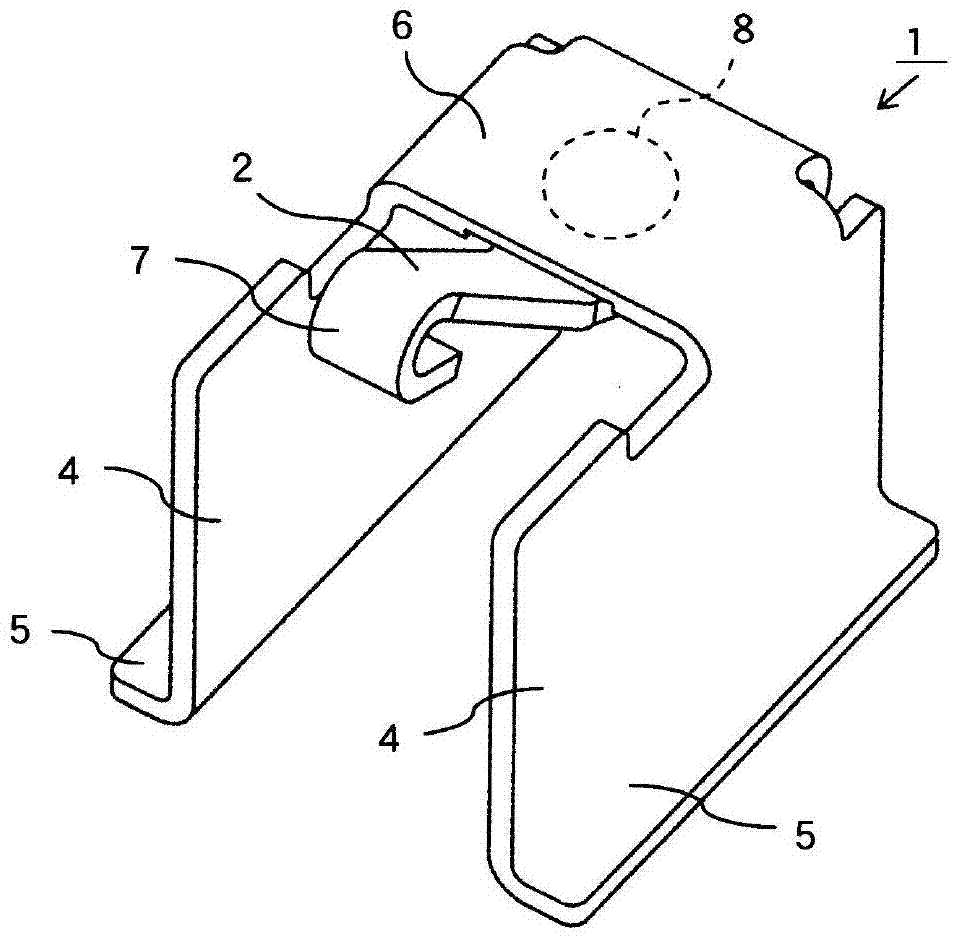
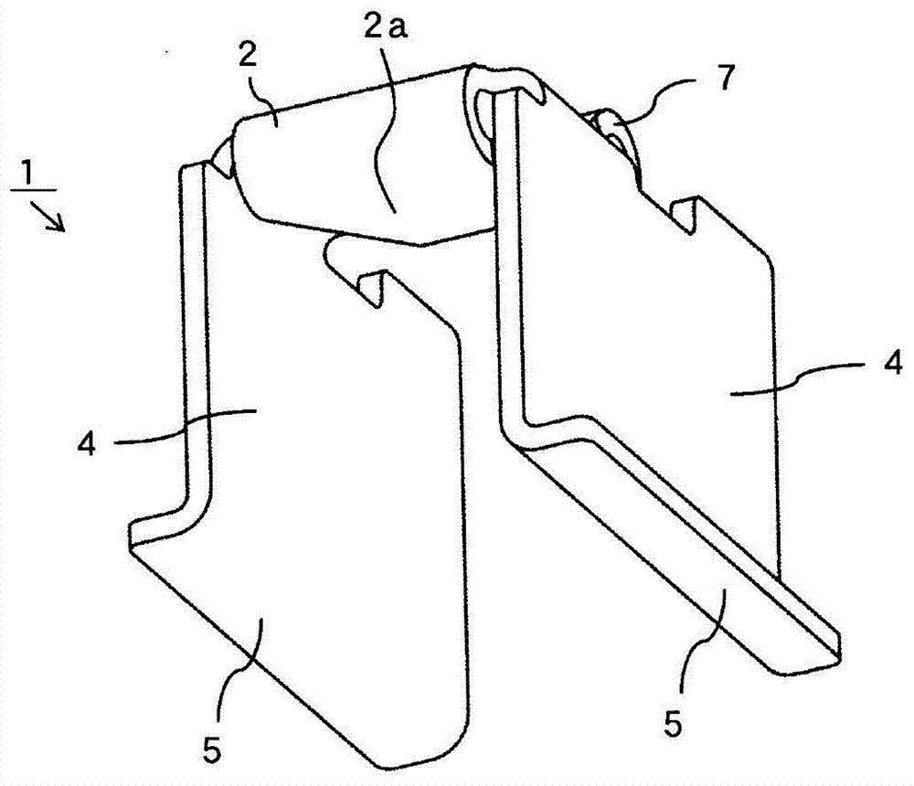
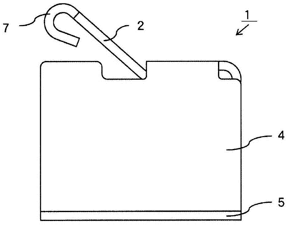
[0071] Below, use Figure 1 ~ Figure 5 as well as Figure 8 (a) The circuit board connection terminal 1 according to an embodiment of the present invention will be described. The circuit board connection terminal 1 is as Figure 5 As shown, the shielding case 10 of the electronic device is electrically connected to the unillustrated grounding pattern of the printed wiring board 11, and the terminal is mounted on the printed wiring board 11 for the purpose of grounding. Therefore, hereinafter referred to as It is the ground terminal 1. Also, in the following description, image 3 The left side is the front, the right side is the rear, and the vertical direction is the same as the vertical direction. Explain the position of each part.

[0072] Terminal 1 for circuit board connection Figure 1 ~ Figure 4 As shown, it is integrally formed of a conductive metal plate with elasticity such as phosphor bronze, titanium copper, etc.: a pair of rectangular plate-shaped legs 4, 4 standing ...


PUM


Abstract

The present invention relates to a terminal for connecting a circuit board. Its object is to provide a circuit board connection terminal that does not change the height of the contact portion of the leaf spring on the circuit board, does not cover the contact portion with solder flux, and can obtain reliable connection to an external conductor. Between the base plate part of the cantilever supporting the leaf spring elastically contacting the external conductor and the soldered connection part, a foot part is formed to support the base plate part in parallel above the circuit board at a set interval, so that the plate The free end side of the reed protrudes from between the base plate portion and the circuit board. The leaf spring is supported at a high position away from the soldered connection, so it will not be covered with flux.

Description

Technical field [0001] The present invention relates to a terminal for connecting a circuit board. A solder connection portion is soldered to a conductive pattern of the circuit board and mounted on the circuit board, so that the conductive pattern of the circuit board is electrically connected to external conductors such as a surrounding shielding plate. ,It relates to a circuit board connection terminal provided with a U-shaped leaf spring that is elastically contacted with an external conductor. Background technique [0002] Various circuit board connection terminals that connect the ground pattern of the printed wiring board to the surrounding shield plate to short-circuit the ground terminal, etc., so that the conductive pattern of the circuit board mounted on the circuit board is electrically connected to the external conductor Known by people. Conventionally, the circuit board connection terminal mounted on the circuit board in this way makes the leaf spring with the spri...

Claims


Application Information

Patent Timeline
Patent Type & Authority Patents(China)
IPC IPC(8): H01R12/71H01R12/57H01R13/24H01R13/648
Inventor 梁濑智康浅井清
Owner SMK CO LTD
Why Eureka
Try Eureka