Support body and method for inspecting magnetic component therewith

A technology of magnetic components and support bodies, applied in the direction of support head, head hydrodynamic spacing, configuration/installation of recording head, etc., can solve problems such as long working time, high-efficiency manufacturing restrictions, complicated fixing operations, etc., to achieve Maintain an easy, less misplaced effect

Active Publication Date: 2007-05-23
TDK CORPARATION
View PDF7 Cites 0 Cited by
  • Summary
  • Abstract
  • Description
  • Claims
  • Application Information

AI Technical Summary

Problems solved by technology

In this way, in the HGA disclosed in Patent Document 2, since the head slider 1 is easily dislocated from the engaging recess 4a, it is necessary to fix the head slider 1 so as not to move toward the open end until the epoxy resin Solidification of other bonding mechanisms
[0014] Therefore, not only the fixing operation of the above-mentioned magnetic head slider 1 and the above-mentioned supporting spring 4 becomes complicated, but also requires a long working time, so the efficient manufacture is limited.
[0015] Moreover, in order to securely fix the above-mentioned magnetic head slider 1 and the above-mentioned support spring 4 in the HGA disclosed in the above-mentioned Patent Document 2, the bonding mechanism such as epoxy resin formed in the above-mentioned support spring fixing groove 3 of the above-mentioned magnetic head slider 1 and the The above-mentioned fitting protruding piece 4b of the above-mentioned support spring 4 is joined, so the above-mentioned magnetic head slider 1 cannot be easily attached to and detached from the upper support spring 4.
[0016] In addition, the above-mentioned HGA disclosed in the above-mentioned patent document 2 does not describe or suggest any method and mechanism for making the conductor extending from the above-mentioned magnetic core chip and the above-mentioned magnetic core chip 2 be electrically connected well.

Method used


Image

  • Support body and method for inspecting magnetic component therewith
  • Support body and method for inspecting magnetic component therewith
  • Support body and method for inspecting magnetic component therewith

Examples


Embodiment Construction

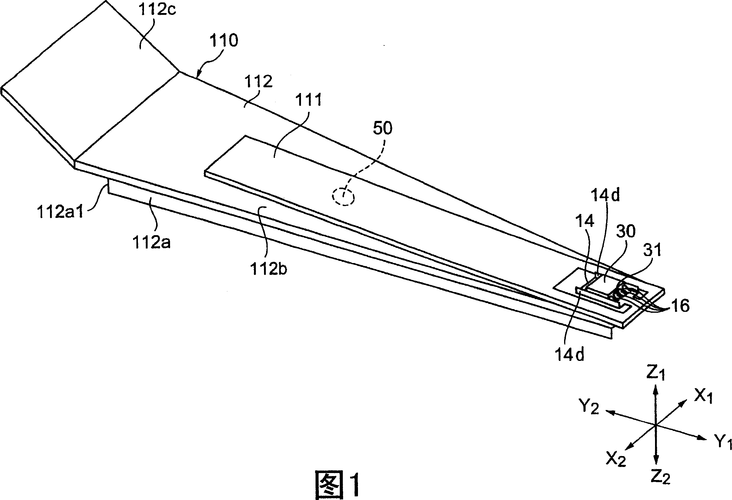
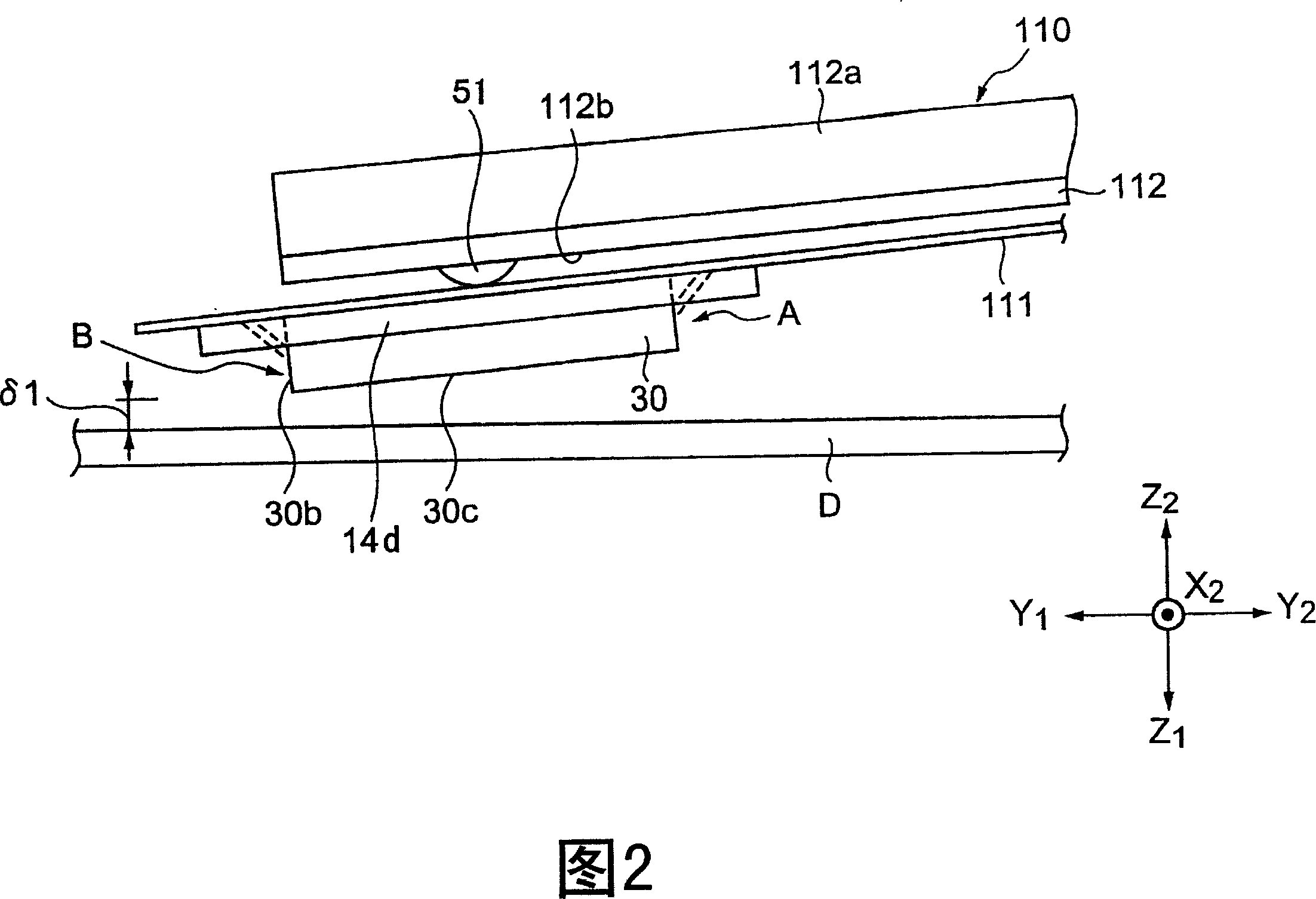
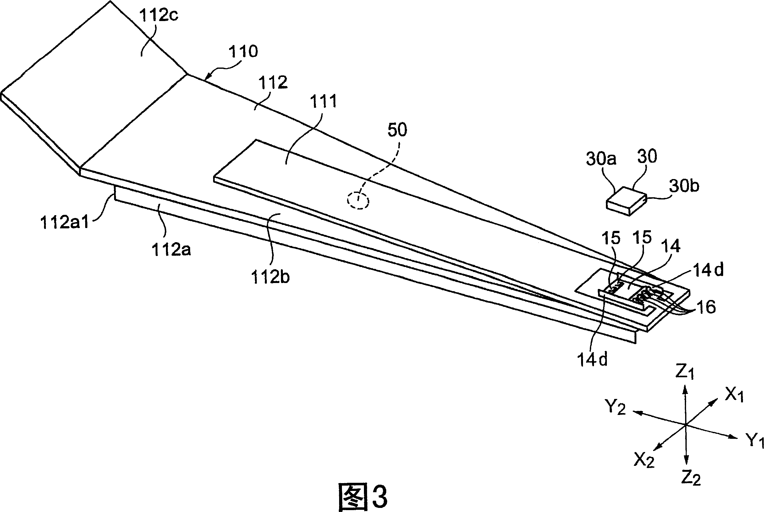
[0054] Fig. 1 is a partial perspective view showing a support body and a sliding body supported on the support body according to an embodiment of the present invention on the side opposite to the recording medium, and Fig. 2 is a diagram showing the side opposite to the recording medium. A partial side view of the supporting body and the sliding body shown in FIG. 1 is shown together with the recording medium in the state of the lower side, and FIG. 3 is an exploded perspective view showing the surface of the supporting body and the sliding body shown in FIG. 1 facing the recording medium. , FIG. 4 is a perspective view of the sliding body held on the support shown in FIG. 1 . In addition, in each figure, the Z1 direction shown is the surface facing a recording medium.

[0055] As shown in FIG. 1 , the support body 110 is composed of a load beam 112 as a first support portion and a flexible plate 111 as a second support portion fixed to the load beam 112 . The flexible plate ...


PUM


Abstract

The present invention provided a highly versatile support capable of performing electric connection between the conductive pattern of the support and a slider, and easily and efficiently executing a slider holding process, and an inspection method using the same. The second support part 11 of a support 110 having conductive patterns 41a and 41b formed is provided with a holding part 14 for holding a slider 30 having a recording and / or reproducing magnetic element 31. A plurality of fixing parts 15 and 16 are formed in the holding part 14 and, when the slider 30 is held between the plurality of fixing parts 15 and 16, the slider 30 is electrically connected to the conductive patterns 41a and 41b.

Description

technical field [0001] The present invention relates to a supporting body for supporting a sliding body on which a magnetic element is formed, and particularly relates to a process capable of making good electrical connection between a circuit formed on the supporting body and the sliding body, and enabling easy and efficient holding of the sliding body. Moreover, the support body has good versatility. [0002] Furthermore, this invention relates to the inspection method of the magnetic element which used the said support body. In particular, it relates to an inspection method of a magnetic element capable of inspecting the dynamic electrical characteristics of a slider before the slider is assembled to a flex plate (flexia) or a state (HGA) on a load beam. Background technique [0003] FIG. 1 or FIG. 9 of the following Patent Document 1 (JP-A-9-213036) discloses a suspension device 3 that functions as a support body for supporting a slider 4 on which a magnetic element is ...

Claims


Application Information

Patent Timeline
Patent Type & Authority Patents(China)
IPC IPC(8): G11B21/21G11B5/60G11B21/26
Inventor 本西道治沢井完次
Owner TDK CORPARATION
Why Eureka
Try Eureka