Connector for cable connection

A connector and cable technology, which is applied in the field of cable connection connectors, can solve the problems of large push resistance, poor adhesion, and time required, so as to reduce the pressure pressure, shorten the heat transfer distance, and reduce the load. Effect

Inactive Publication Date: 2012-02-22
HONDA TSUSHIN IND
View PDF1 Cites 0 Cited by
  • Summary
  • Abstract
  • Description
  • Claims
  • Application Information

AI Technical Summary

Problems solved by technology

[0005] However, in the above-mentioned prior art example 1, the heat of the heater chip 25 is transmitted along a long distance in a state parallel to the conductor 24a or 24b, the contact 23, and the protrusion 22, so it takes time to melt the protrusion 22, and the heater chip The lower surface of 25 first abuts against the upper end of the conductor 24b with a thick diameter, and after the protrusion 22b is deformed and descends, it abuts against the upper end of the conductor 24a with a thin diameter. For soldering, the time must be adjusted so that the soldering on the side of the conductor 24b with a large diameter will not be overheated, and the pushing resistance is also large.
[0006] In addition, in the above-mentioned prior art example 2, such as Figure 11 As shown, the deflection of the contact 23 in the pushing direction creates a gap c between the conductor 24 and the contact 23, which may cause poor adhesion between them.
Furthermore, although it is not shown in the figure, a technique is known in which various cutouts are provided on the heater sheet so as to contact the upper parts of conductors with different diameters on a straight line. However, this turns the heater sheet into a dedicated heater sheet. , has the disadvantage of not being universal

Method used


Image

  • Connector for cable connection
  • Connector for cable connection
  • Connector for cable connection

Examples


Embodiment Construction

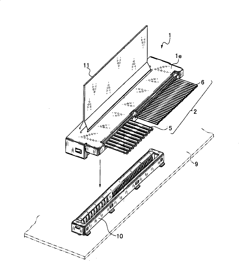
[0031] The cable connection connector 1 related to the present invention is as Figure 1 ~ Figure 3B As shown, the connector is used to connect the conductors of the cable assembly 2 ( 5a, 5b, . . . and 6a, 6a, . . . ) are collectively connected to contact 4 . like figure 1 As shown, the cable connection connector 1 is fitted with a connector receptacle 10 mounted on a printed circuit board 9 and is provided with a handle 11 for attachment and detachment.

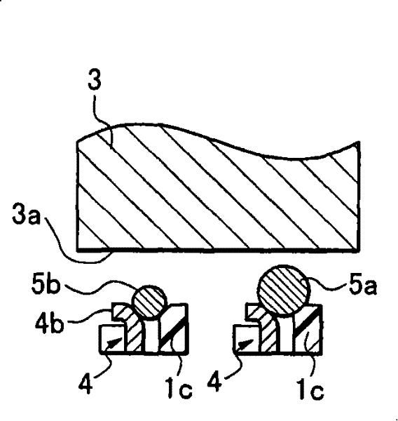
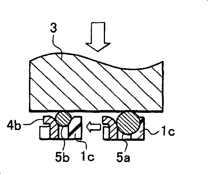
[0032] like figure 1 and Figure 4A As shown, the connector 1 for cable connection is composed of: a laterally elongated insulating housing 1a, and conductors 5a, 5b, 5c of discrete wires 5 arranged in a direction substantially perpendicular to the longitudinal direction of the insulating housing 1a. .. a plurality of contacts 4, 4 ... connected, contacts 7, 7 connected with conductors 6a, 6a ... of a plurality of thin-wire coaxial lines 6, and protruding between contacts 4, 4 The thermoplastic clamping root 1c is fo...


PUM


Abstract

The present invention provides a connector for cable connection that reduces resistance and improves connection strength between conductors and contacts by collectively soldering cables with different diameters. a contact, and a thermoplastic clamping root; the insulating housing is long in the transverse direction; The length direction of the casing is arranged in a line orthogonally; the thermoplastic clamping root protrudes from the flat surface of the insulating casing between each contact and toward the connecting portion.

Description

technical field [0001] The invention relates to a connector used for connecting multiple cables when connecting electronic devices such as computers. The connector is used to connect multiple cables with different wire diameters to A connector for cable connection on contacts in the connector for connection. Background technique [0002] In the prior art, in order to connect groups of different-diameter cables with different wire diameters together, it is known, for example Figure 9A and 9B As shown in the connector for cable connection (refer to Japanese Patent Laid-Open No. 2004-87388), the connector for cable connection is formed at the insulating housing part where the connection terminal of the connector is arranged to abut against the connection terminal and can Deformed protrusions. [0003] In the above-mentioned connector for cable connection, the protrusions 22 a and 22 b protruding upward from the insulating case 21 forming the connector have a height capable o...

Claims


Application Information

Patent Timeline
Patent Type & Authority Patents(China)
IPC IPC(8): H01R4/02H01R13/46
CPCH01R12/592H01R43/0249H01R43/0221
Inventor 宫崎诚布川智治
Owner HONDA TSUSHIN IND
Why Eureka
Try Eureka