Cooling spray tower

A cooling tower and spray tower technology, applied in the field of cooling towers, can solve the problems of reduced cooling efficiency, large air intake resistance, and low cooling efficiency, and achieve the effect of improving cooling efficiency, less air intake resistance, and good pre-cooling effect

Inactive Publication Date: 2015-11-11
CHENGDU JIAMEIJIA SCI & TECH
View PDF15 Cites 1 Cited by
  • Summary
  • Abstract
  • Description
  • Claims
  • Application Information

AI Technical Summary

Problems solved by technology

[0002] At present, in the cooling system, the method of water cooling is usually used to cool down, and in order to make the cooling faster, a ventilation device is installed in the cooling tower, and the cooling water is cooled by the circulation of air, but the ventilation device is used to cool the cooling water. The cooling efficiency is not high, resulting in a waste of energy. In addition, some cooling towers are used to cool down. However, the airflow in the cooling tower is not evenly distributed, which reduces the cooling efficiency to a certain extent. Interference greatly affects the instability of the work, resulting in affecting the final cooling effect, and cannot complete the cooling better

Method used


Image

  • Cooling spray tower

Examples


Embodiment Construction

[0012] The present invention will now be described in further detail in conjunction with the accompanying drawings, which are simplified schematic diagrams, only schematically illustrating the basic structure of the present invention, and therefore only show the configurations related to the present invention.

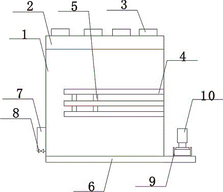
[0013] Such as figure 1 The preferred embodiment of the shown cooling spray tower of the present invention comprises a cooling tower body 1, the cooling tower body 1 is equipped with an air inlet device 2 near the top, the air inlet device 2 is fixed on the cooling tower body 1, and the air inlet device 2 The upper surface is connected with an air inlet pipe 3, more than one air inlet pipe 3, and the air inlet pipe 3 is evenly arranged on the air inlet device 2, and the air inlet pipe 3 and the air inlet device 2 are detachably connected, and the cooling tower body 1 There is a pre-cooling layer 4 inside, and one end of the pre-cooling layer 4 is fixed on the inner wal...


PUM


Abstract

The invention discloses a cooling spray tower. The cooling spray tower comprises a cooling tower body. An air inlet device is arranged at the position, close to the top, of the cooling tower body and is fixed to the cooling tower body. The upper surface of the air inlet device is connected with more than one air inlet pipe. The air inlet pipes are evenly arranged on the air inlet device. The air inlet pipes are detachably connected with the air inlet device. Pre-cooling layers are arranged in the cooling tower body. One end of each pre-cooling layer is fixed to the inner wall of the cooling tower body. Shifting pieces are connected to the pre-cooling layers. The shifting pieces are connected with the pre-cooling layers in a sliding manner. A water collection tank is arranged at the bottom of the cooling tower body. The cooling tower body and the water collection tank are communicated and connected. By means of the cooling spray tower, the stability of air flow entering the tower can be better improved; the influences of the wind force of the atmosphere on the cooling tower can be effectively avoided; the air inlet resistance is small; the air flow is smooth; the cooling efficiency is greatly improved; pre-cooling can be conveniently conducted; the pre-cooling effect is quite good; and therefore the cooling efficiency is greatly improved, and energy is effectively saved to a certain extent.

Description

technical field [0001] The invention relates to a cooling tower, in particular to a cooling spray tower. Background technique [0002] At present, in the cooling system, the method of water cooling is usually used to cool down, and in order to make the cooling faster, a ventilation device is installed in the cooling tower, and the cooling water is cooled by the circulation of air, but the ventilation device is used to cool the cooling water. The cooling efficiency is not high, resulting in a waste of energy. In addition, some cooling towers are used to cool down. However, the airflow in the cooling tower is not evenly distributed, which reduces the cooling efficiency to a certain extent. Interference greatly affects the instability of the work, resulting in affecting the final cooling effect, and cannot complete the cooling better. Contents of the invention [0003] The technical problem to be solved by the present invention is: to overcome the above problems, to provide ...

Claims


Application Information

Patent Timeline
Patent Type & Authority Applications(China)
IPC IPC(8): F28C1/00F28F25/06
Inventor 梁枫
Owner CHENGDU JIAMEIJIA SCI & TECH
Why Eureka
Try Eureka