Method for obtaining antifriction and wear-resistant workpiece surface through lasers

A workpiece surface, laser technology, applied in the field of friction pair lubrication, can solve problems such as difficult machining, affecting the surface roughness of the friction pair, and shortening the fatigue life of the friction pair surface, so as to improve wear resistance, reduce friction, and improve fatigue life. Effect

Inactive Publication Date: 2015-11-11
JIANGSU UNIV
View PDF7 Cites 16 Cited by
  • Summary
  • Abstract
  • Description
  • Claims
  • Application Information

AI Technical Summary

Problems solved by technology

With the deepening of the understanding of the traditional laser micro-modeling technology, people realize that the traditional laser micro-modeling technology has the following shortcomings: (1) the integrity of the surface of the friction pair is destroyed during the ablation process; (2) the high temperature during the ablation process will The surface of the friction pair produces residual tensile stress, which will shorten the fatigue life of the surface of the friction pair; (3) there are burrs near the processed micro-pit, and the heat-affected zone affects the roughness of the surface of the friction pair; (4) it is difficult to Micro-dimples with large diameter and depth are processed, making it difficult to store lubricants, especially solid lubricants

Method used


Image

  • Method for obtaining antifriction and wear-resistant workpiece surface through lasers
  • Method for obtaining antifriction and wear-resistant workpiece surface through lasers
  • Method for obtaining antifriction and wear-resistant workpiece surface through lasers

Examples


Embodiment Construction

[0023] The present invention will be further described below in conjunction with the accompanying drawings and specific embodiments, but the protection scope of the present invention is not limited thereto.

[0024] A method for obtaining the surface of a friction-reducing and wear-resistant workpiece by using a laser, comprising the following steps:

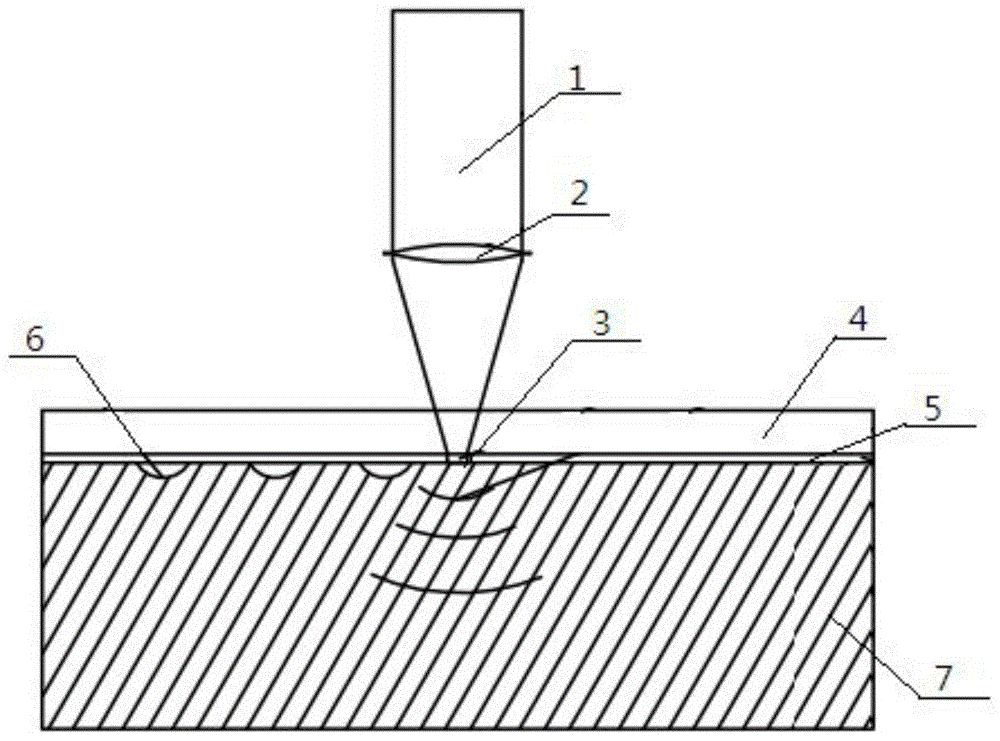
[0025] Step A: laser microshock treatment; as figure 1 As shown, the absorbing layer 5 is coated on the surface of the workpiece 7, and then the constraining layer 4 is covered on the absorbing layer 5. The absorbing layer is black insulating tape with a thickness of 0.5mm; the constrained layer is K9 glass with a thickness of 1mm; according to the workpiece The diameter D of the microhole 9 required on the surface of 7 adjusts the process parameters of the laser; then the laser is driven so that the laser shock beam 1 is focused by the focusing lens 2 and then irradiates the surface of the workpiece 7 to obtain a micropit 6 who...


PUM


Abstract

The invention provides a method for obtaining an antifriction and wear-resistant workpiece surface through lasers. The method comprises the steps that laser micro-impact treatment is carried out, wherein the workpiece surface is coated with an absorption layer, the absorption layer is covered with a restraint layer, the technological parameters of a laser device are adjusted, laser beams irradiate the workpiece surface for impacting after being focused by a lens, and micro pits are obtained; laser micro drilling treatment is carried out, wherein the absorption layer and the restraint layer on the workpiece surface are removed, the laser device is replaced, laser drilling light beams are adjusted to be aligned to the centers of the micro pits, the technological parameters of the laser device are adjusted to carry out micro drilling treatment on a workpiece, then micro holes are obtained, and the relation between the laser spot diameter c in the micro drilling treatment process and the laser spot diameter C in the micro impacting process is c=(0.15-0.25)C; and the antifriction and wear-resistant workpiece surface is machined according to the number and distance of the obtained micro holes needed by the workpiece surface. The micro holes with the large diameter and large depth are machined, a lubricant is placed in the micro holes to reduce friction and wear of the contact surface of a friction pair, and then the wear resisting performance of the surface of the friction pair is improved.

Description

technical field [0001] The invention belongs to the technical field of friction pair lubrication, and in particular relates to a method for obtaining the surface of a friction-reducing and wear-resistant workpiece by using a laser, which is used to improve the wear resistance of the friction pair surface. Background technique [0002] Friction pairs are ubiquitous in mechanical motion. In recent years, with the gradual improvement of the surface lubrication performance requirements for important friction pair functions, surface micro-modeling technology has developed rapidly due to its excellent lubrication performance. At present, various surface engineering technologies have been applied to surface texturing, among which laser surface micro-modeling technology has been widely used because of its high efficiency and good process performance. The traditional laser surface micro-modeling technology relies on the laser beam with high energy density after focusing, and realizes...

Claims


Application Information

Patent Timeline
IPC IPC(8): B23K26/352B23K26/18B23K26/382C21D10/00
CPCB23K26/18B23K26/356C21D10/005
Inventor 王匀柏云杜金星王建杰杨夏明许桢英殷苏民
Owner JIANGSU UNIV
Why Eureka
Try Eureka