Gas cooler

A technology of gas coolers and cooling chambers, applied in gaseous chemical plating, chemical instruments and methods, lighting and heating equipment, etc., which can solve problems such as increasing driving force, increasing sliding resistance, and enlarging the overall size of the device

Active Publication Date: 2015-11-04
JFE STEEL CORP
View PDF6 Cites 6 Cited by
  • Summary
  • Abstract
  • Description
  • Claims
  • Application Information

AI Technical Summary

Problems solved by technology

In addition, if the sealing performance of the sliding part is enhanced in order to improve the sealing effect, the sliding resistance increases accordingly, and the driving force needs to be f

Method used


Image

  • Gas cooler

Examples


Embodiment Construction

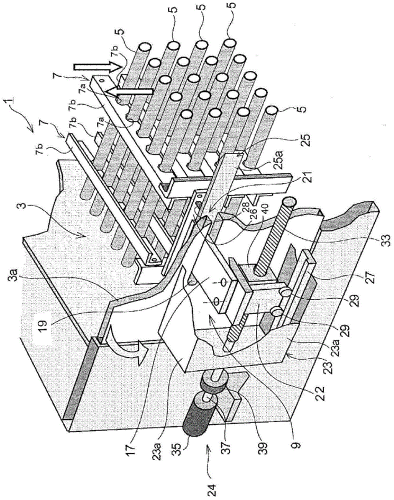
[0030] based on figure 1 The gas cooler 1 according to this embodiment will be described.

[0031] like figure 1 As shown, the gas cooler 1 of the present embodiment includes: a plurality of cooling pipes 5 arranged in parallel in the cooling chamber 3 through which the gas flows; ; And the reciprocating mechanism 9, which makes the dust removal member 7 reciprocate along the axial direction of the cooling pipe 5.

[0032] Hereinafter, each configuration will be described in detail.

[0033]

[0034] The cooling chamber 3 is a chamber for the circulation of exhaust gas, and the exhaust gas such as figure 1 As shown by the arrow of , it flows in a direction orthogonal to the cooling pipe 5 (from bottom to top, or from top to bottom).

[0035] The side wall 3a of the cooling chamber 3 has a door structure, and can be opened and closed as shown by the arrow in the figure. By providing the side wall 3a to be openable and closable, maintenance such as replacement of the dust...


PUM


Abstract

Provided is a gas cooler which is reduced in size, is configured so as to prevent discharge gas from leaking to the outside, and enables dust to be consistently brushed off. This gas cooler (1) has: cooling pipes (5) which are arranged within a cooling chamber (3); a dust brush-off member (7) which is provided in a slidable manner on the peripheral surfaces of the cooling pipes; and a reciprocation mechanism (9) which is capable of reciprocating the dust brush-off member in the axial direction of the cooling pipes. The reciprocation mechanism is provided with: a holding member (17) which holds the dust brush-off member so that the dust brush-off member is capable of reciprocating and which extends in the direction intersecting the axial direction of the cooling pipes; an opening (19) which is provided in a side wall (3a) of the cooling chamber and which enables the holding member to extend out of the cooling chamber and reciprocate; a seal mechanism (21) which prevents gas within the cooling chamber from leaking to the outside; a movement body (22) which supports the holding member extending out of the opening and which is capable of reciprocating; and a drive means (24) which reciprocates the movement body.

Description

technical field [0001] The present invention relates to an exhaust gas containing dust such as a gas cooler (exhaust gas cooling device) that cools exhaust gas of a facility for producing high-concentration silicon steel strips by silicon infiltration treatment by CVD (chemical vapor deposition). Gas cooler for gas cooling. Background technique [0002] The exhaust gas of the furnace plant for the production of high silicon steel strip contains ferrous chloride (FeCl 2 , hereinafter referred to as ferric chloride), this substance has the physical properties of a boiling point of 1024 °C and a melting point of 670 °C. [0003] When the exhaust gas is rapidly cooled from the furnace temperature to below the melting point, ferric chloride is produced as fine powder in the exhaust gas. When the exhaust gas is further cooled from this temperature by the gas cooler, ferric chloride (dust) adheres to the heat transfer surface of the gas cooler. Therefore, dust removal devices ar...

Claims


Application Information

Patent Timeline
IPC IPC(8): F28G1/08B08B1/00C23C16/44
CPCB08B1/008B08B9/023C23C16/4412F28G1/08
Inventor 古贺泰成富永健一堤道明
Owner JFE STEEL CORP
Why Eureka
Try Eureka