Feeding device of die cutting machine

A technology of feeding device and die-cutting machine, which is applied in metal processing and other directions, can solve the problems of affecting die-cutting accuracy, easy to swing in feed, unstable control of tension of die-cutting raw materials, etc., and achieves high die-cutting accuracy and tension control. Stable, not easy to swing effect

Inactive Publication Date: 2015-11-04
TONGCHENG FURUN PACKAGING MATERIAL
View PDF5 Cites 4 Cited by
  • Summary
  • Abstract
  • Description
  • Claims
  • Application Information

AI Technical Summary

Problems solved by technology

At present, the common die-cutting machines in the market do not have a feeding device, or only rely on multiple guide rollers to control the tension of the material, which makes the tension control of the die-cutting raw material unstable, and the feeding is prone to swing, which affects the die-cutting accuracy.

Method used


Image

  • Feeding device of die cutting machine

Examples


Embodiment Construction

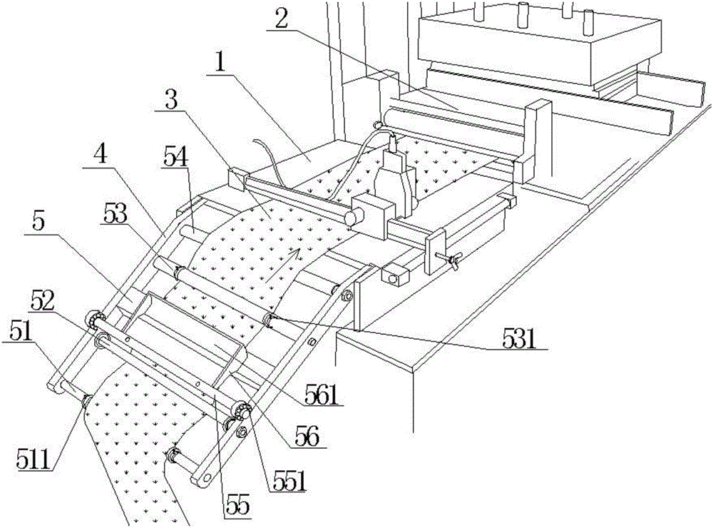
[0017] Such as figure 1 , a feeding device for a die-cutting machine, which is arranged on one side of the feeding table 1, and the other side of the feeding table 1 is provided with a die-cutting device 2 of the die-cutting machine. The feeding device of the die-cutting machine includes support arms 4 on both sides and connecting rods 5 connecting the supporting arms 4. The connecting rods 5 are arranged in a rectangular strip shape, wherein the four square corners of the connecting rods 5 are rounded. It is not easy to cause scratches to the die-cutting raw material 3 .

[0018] The first round bar 51, the second round bar 52, the third round bar 53, and the fourth round bar 54 are arranged between the two arms 4, wherein the first round bar 51 and the second round bar 52 are arranged on the connecting rod 5 On one side, the third round rod 53 and the fourth round rod 54 are arranged on one side and the other side of the connecting rod 5 . The arrangement of multiple round...


PUM


Abstract

The invention discloses a feeding device of a die cutting machine. The feeding device comprises support arms on the two sides and a connecting rod for connecting the support arms. A first round rod, a second round rod, a third round rod, a fourth round rod and an auxiliary rod are arranged between the two support arms. The auxiliary rod is provided with an externally-arranged pressing plate. The pressing plate is provided with a pressing trough. The feeding device of the die cutting machine is arranged on one side of a feeding table, and a die cutting device is arranged on the other side of the feeding table. The first round rod is provided with two slideable first fixing rings. The third round rod is provided with two slideable second fixing rings. The first fixing rings are fixed to the first round rod through bolts, and the second fixing rings are fixed to the third round rod through bolts. The lower side of the pressing plate is in a smooth arc shape, and the pressing plate is fixed to the auxiliary rod through bolts. The feeding device of the die cutting machine is simple, applicable and convenient to use. The tension of die-cutting raw materials is controlled stably, the die-cutting raw materials are not prone to swinging, and the die cutting precision is high.

Description

technical field [0001] The invention relates to the field of die-cutting machine mechanical devices, in particular to a die-cutting machine feeding device. Background technique [0002] Die-cutting machine is also called beer machine, cutting machine, CNC punching machine, mainly used for die-cutting of corresponding non-metallic materials, self-adhesive, EVA, double-sided adhesive, electronics, mobile phone rubber pad, etc. breaking), indentation and hot stamping operations, lamination, automatic waste discharge, etc. The die-cutting machine uses steel knives, metal molds, steel wires (or templates carved from steel plates), and applies a certain pressure through the embossing plate to roll and cut printed products or cardboard into a certain shape. It is an important equipment for post-press packaging processing. . At present, the common die-cutting machines on the market do not have feeding devices, or only rely on multiple guide rollers to control the tension of the ma...

Claims


Application Information

Patent Timeline
Patent Type & Authority Applications(China)
IPC IPC(8): B26D7/01B26D7/14
Inventor 杨峰
Owner TONGCHENG FURUN PACKAGING MATERIAL
Why Eureka
Try Eureka