
Maximum gain direction-adjustable monopole antenna

A monopole antenna, maximum gain technology, applied in the field of communication, can solve the problems of wasting materials, prolonging the design cycle, increasing the design cost, etc., and achieving the effects of low cost, reduced production cost, and high reliability

Active Publication Date: 2015-10-28
NAT ASTRONOMICAL OBSERVATORIES CHINESE ACAD OF SCI
View PDF6 Cites 2 Cited by
  • Summary
  • Abstract
  • Description
  • Claims
  • Application Information

AI Technical Summary

Problems solved by technology

[0005] However, the satellite altitude angle will also change with the change of the working place. In order to maintain normal communication, the maximum gain pointing angle of the antenna pattern will also change. If the traditional conical beam antenna needs to adjust the maximum gain pointing of the beam, the antenna needs to be redesigned. This not only prolongs the design cycle, but also increases the design cost, and wastes materials

Method used

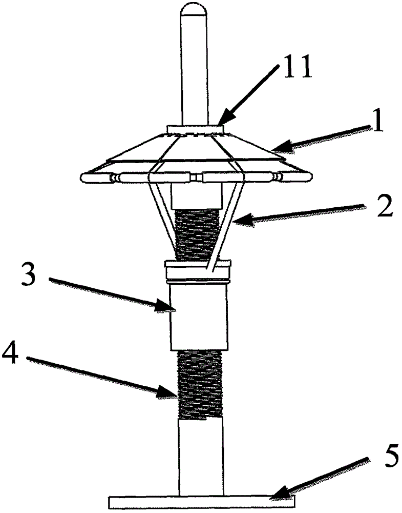
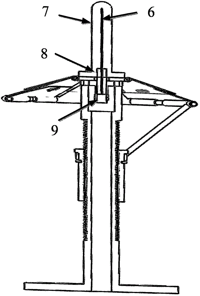

Image

  • Maximum gain direction-adjustable monopole antenna
  • Maximum gain direction-adjustable monopole antenna
  • Maximum gain direction-adjustable monopole antenna

Examples


Embodiment Construction

[0032] The present invention will be further described in conjunction with the embodiments and accompanying drawings. This embodiment is implemented on the premise of the technical solution of the present invention. The detailed implementation and specific operation process are given, but the protection scope of the present invention is not limited to the following examples.

[0033] The contents not described in detail in the specification belong to the prior art known to those skilled in the art.

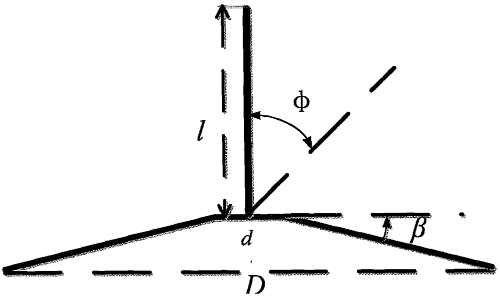
[0034] figure 1 A schematic diagram of the folding angle β of the reflector, the maximum diameter D, the diameter of the upper surface (that is, the diameter of the central body) d, and the length l of the vibrator is given. The specific plan is:

[0035] (1) Determine the length l of the vibrator according to the operating frequency point, and consider the influence of the vibrator protective cover on the operating frequency point and bandwidth of the antenna. Due to the infl...


PUM


Abstract

The present invention discloses a maximum gain direction-adjustable monopole antenna, which comprises an oscillator, an oscillator protection cover, a base and an insulating medium. The oscillator is embedded at the center of the oscillator protection cover. The oscillator and the oscillator protection cover define the center frequency point and the bandwidth of the antenna during operation. The antenna also comprises a reflecting plate and a reflecting plate angle adjusting device. The lower part of the reflecting plate angle adjusting device is connected with the base. The upper part of the reflecting plate angle adjusting device is connected with the reflecting plate. The reflecting plate is in the form of a folding type reflecting plate. The folding angel of the reflecting plate can be changed by the reflecting plate angle adjusting device, so that the maximum gain direction of the monopole antenna is changed. According to the technical scheme of the invention, the angle of the maximum gain direction of the antenna can be conveniently and quickly adjusted. At the same time, the impedance bandwidth of the antenna is ensured to be unchanged.

Description

technical field [0001] The invention belongs to the technical field of antennas in the communication field, and relates to a satellite communication antenna, in particular to a monopole antenna with adjustable maximum gain direction. Background technique [0002] Low information rate satellite communication technology plays a huge role in the fields of earthquake relief and ocean exploration, and it is also one of the effective means of communication in remote areas that cannot be covered by ground communication networks. The antenna pattern of the low information rate satellite communication terminal adopts a conical beam, and the maximum gain in the pitch direction of the antenna pattern points to the satellite. [0003] Maximum gain pointing refers to the angle at which the maximum gain deviates from the central axis of the antenna, see figure 1 , φ angle is the maximum gain pointing angle. [0004] Known antennas that can generate conical beams include: circular patch ...

Claims


Application Information

Patent Timeline
IPC IPC(8): H01Q3/20
Inventor 庞峰艾国祥胡超马利华王晓岚李圣明王鹏马月
Owner NAT ASTRONOMICAL OBSERVATORIES CHINESE ACAD OF SCI
Learn More