
Ground antenna and ground radiator using capacitor

a capacitor and capacitor technology, applied in the direction of slot antennas, antenna details, antennas, etc., can solve the problems of large amount of fabrication cost, complex fabrication process, and inability to apply devices in a wide range of applications, and achieve the effect of simplifying the antenna structure, simplifying the radiator structure, and excellent radiation performan

Inactive Publication Date: 2014-03-06
RADINA
View PDF6 Cites 7 Cited by
  • Summary
  • Abstract
  • Description
  • Claims
  • Application Information

AI Technical Summary

Benefits of technology

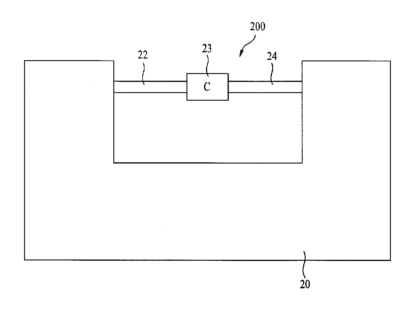
The present invention provides an antenna that has excellent radiation performance while simplifying the structure of the antenna that can perform ground radiation. The simplification of the structure of the radiator reduces fabrication costs and makes the fabrication process easier. Additionally, the invention provides an antenna that can still perform effectively even when a mobile communication terminal's surface is covered with a conductive substance such as LCD.

Problems solved by technology

Therefore, the above-described antenna shall only be used in a user terminal (e.g., folder type user terminal) being configured of two sub-bodies, and, since the electric conductor for inductive coupling is decided to have a constant length, there lie many problems in that the structure is not simple, and that the scope of devices that can be applied is also very limited.
And, in order to manufacture such a complex structure, a considerable amount of fabrication cost and complex fabrication process have been required.
Therefore, although the related art ground radiation antenna uses the ground as its radiator, it still requires a separate radiation structure having a complex structure.
And, in order to implement such a radiation structure, a considerable amount of fabrication cost has been required.
Moreover, as the radiation structure of the antenna becomes more complex, there have been limitations in creating slimmer user terminals.
Most particularly, the related art ground radiation antenna is disadvantageous in that the essential phenomenon of ground radiation was not fully nor well understood, and, accordingly, due to an unnecessarily complex structure for implementing such ground radiation, the fabrication cost has increased, and the fabrication process has become complicated.

Method used


Image

  • Ground antenna and ground radiator using capacitor
  • Ground antenna and ground radiator using capacitor
  • Ground antenna and ground radiator using capacitor

Examples


Embodiment Construction

Technical Objects

[0011]An object of the present invention is to simplify the fabrication process, to create a slimmer antenna, and to remarkably reduce the fabrication cost, by removing the radiation structure having a complex structure and by implementing the ground radiator using only simple elements.

Technical Solutions

[0012]The present invention provides a ground radiator having a more remarkably simplified structure by using a capacitance of a capacitor and an inductance of a ground.

[0013]Additionally, in the ground radiator, the present invention provides a ground radiator that is generated by using only a capacitive element without using a separate radiation structure.

[0014]Furthermore, by spacing apart at least a portion of a radiator configuration circuit from a ground substrate at a predetermined distance, the present invention provides a ground radiator having excellent radiation performance, even when a surface of a mobile communication terminal is covered with a conducti...


PUM


Abstract

By providing a radiator configuration circuit and a feeding circuit each having a simple structure, a ground radiation antenna having a more simplified fabrication process as well as a remarkably reduced fabrication cost is provided herein. Additionally, a ground radiation antenna having an excellent radiation performance, even when one side of a mobile communication terminal is covered with a conductive substance, such as an LCD panel, is also provided herein.

Description

[0001]This application claims the benefit under 35 U.S.C. §120 and §365(c) to a prior PCT International Application No. PCT / KR2012 / 001027, filed on Feb. 10, 2012, which claims the benefit of Korean Patent Application No. 10-2011-0031913, filed on Apr. 6, 2011, and Korean Patent Application No. 10-2011-0113754, filed on Nov. 3, 2011, the contents of which are all hereby incorporated by reference herein in their entirety.FIELD OF THE INVENTION[0002]The present invention relates to a ground radiator configuring a ground radiation antenna and, more particularly, to a ground radiator that can remarkably simplify a structure of the ground radiation antenna.BACKGROUND ART [0003]As a device receiving an RF signal existing in the air inside a user terminal or transmitting a signal existing inside the user terminal to the outside, an antenna corresponds to an essential device used in wireless communication. Recently, as mobile communication terminals have become more compact and light-weight,...

Claims


Application Information

Patent Timeline
Patent Type & Authority Applications(United States)
IPC IPC(8): H01Q1/48
CPCH01Q1/48H01Q1/243H01Q13/10H01Q1/24H01Q13/08
Inventor JANG, HYUN MINCHOI, HYENG CHEULLEE, DONG RYEOLLIU, YANGLEE, HYUNG JINYU, JAE KYU
Owner RADINA
Learn More