Spiral or helical counterflow heat exchanger

A technology of heat exchangers and exchangers, applied in the direction of indirect heat exchangers, heat exchanger types, lighting and heating equipment, etc., can solve the problem that flat and corrugated double-sided enamelled steel plates are not suitable for partition walls, and cannot be spiral or Helical winding and other problems to achieve the effects of simplified production, low cost, and high thermal efficiency

Active Publication Date: 2015-10-21
POLYVISION NV
View PDF8 Cites 8 Cited by
  • Summary
  • Abstract
  • Description
  • Claims
  • Application Information

AI Technical Summary

Problems solved by technology

[0016] For these applications, known corrugated double-sided enamelled steel sheets are not suitable for use in dividing walls as they are not flat and cannot be wound in coils or spirals

Method used


Image

  • Spiral or helical counterflow heat exchanger
  • Spiral or helical counterflow heat exchanger
  • Spiral or helical counterflow heat exchanger

Examples


Embodiment Construction

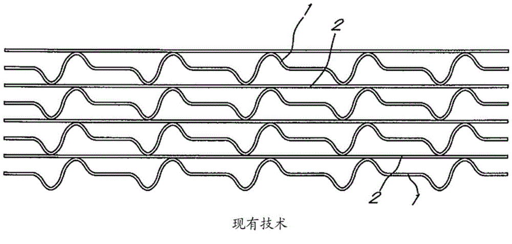
[0046] figure 1 Schematically shows a cross-section of a plurality of corrugated double-sided enamelled steel sheets, used in prior art housings for regenerative heat exchangers. In this case, cold-rolled corrugated steel sheets 1 painted on both sides alternate with flat double-sided enamelled steel sheets 2 .

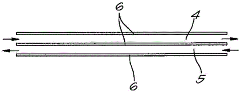
[0047] figure 2 Schematically shows a cross-section of the simplest counterflow heat exchanger 3 according to the invention, comprising two chambers 4, 5 separated from each other by a flat thin double-sided enamelled steel plate 6, at two different temperatures Fluid flows through the two chambers 4, 5 in opposite directions.

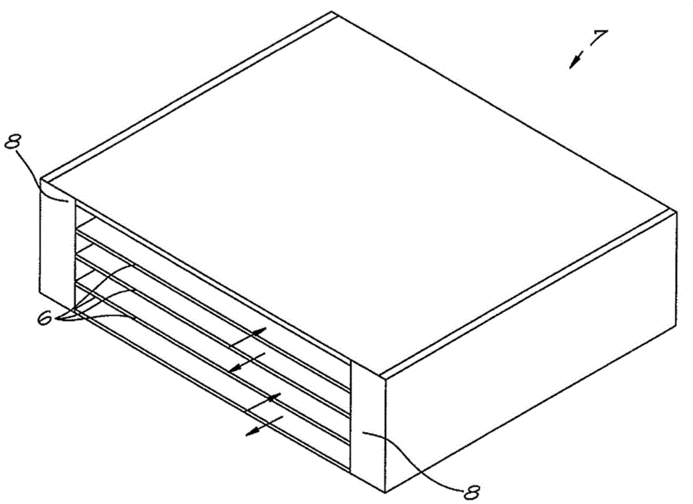
[0048] image 3 A perspective view is schematically shown of a counterflow heat exchanger 7 comprising a stack of flat double-sided enamelled steel sheets 6 , the edges of which are held on corrosion-resistant partitions 8 .

[0049] Figure 4 show image 3 variant, whereby a stack of flat double-sided enamelled steel sheets 6 is separa...


PUM


Abstract

Counterflow heat exchanger consisting of two adjoining chambers, in which a fluid at a high temperature flows in one chamber in one direction, and in which a fluid at a low temperature flows in the opposite direction in the other chamber, characterised in that both chambers are separated by a separating plate of flat monolithic double-sided enamelled steel annealed at temperatures above 500°C, and which together form a spiral or helical heat exchanger.

Description

technical field [0001] The present invention relates to heat exchangers. [0002] More specifically, the invention aims at obtaining a spiral or spiral heat exchanger using enamelled steel. Background technique [0003] The beneficial properties of enamelled steel are generally known, such as high corrosion resistance, high wear resistance and high chemical resistance. [0004] Due to the aforementioned properties, and also because such enamelled steel surfaces are easy to maintain and resistant to high temperatures, the use of enamelled steel in heat exchangers is also known. In addition, enamelled steel has high thermal efficiency for heat conduction due to the thin ceramic layer. [0005] The use of double-sided enamelled corrugated steel sheets is standard in air preheaters and air-to-air heat exchangers in industrial processes, for example in desulfurization plants for combustion gases. [0006] These heat exchangers are in the form of large shells fitted with corrug...

Claims


Application Information

Patent Timeline
Patent Type & Authority Applications(China)
IPC IPC(8): F28D9/00F28F19/02
CPCF28F19/02F28D7/022F28D9/00F28D9/0062F28D9/04
Inventor W.范德布罗克
Owner POLYVISION NV
Why Eureka
Try Eureka