
Sinking device and method for well point drawdown pipe of liquid soil layer

A downwater pipe and well point technology, which is applied in construction, infrastructure engineering, etc., can solve the problems of low efficiency of well point downpipe settlement and failure of well point downpipe settlement, etc., and achieves rapid settling, convenient operation and practicality , the effect of simple structure

Active Publication Date: 2015-10-14
河北二十冶建设有限公司
View PDF3 Cites 6 Cited by
  • Summary
  • Abstract
  • Description
  • Claims
  • Application Information

AI Technical Summary

Problems solved by technology

[0004] One of the objectives of the present invention is to provide a settling device for well point downpipes in fluid soil layers to solve the problem in the prior art that the well hole wall will shrink back to its original shape after the well hole is formed under the condition of fluid soil layers. The problem that the well point downpipe cannot be settled
[0005] The second object of the present invention is to provide a method for settling well point downpipes in fluid soil layers, so as to solve the problem of low efficiency of well point downwater settling

Method used


Image

  • Sinking device and method for well point drawdown pipe of liquid soil layer
  • Sinking device and method for well point drawdown pipe of liquid soil layer
  • Sinking device and method for well point drawdown pipe of liquid soil layer

Examples


Embodiment 1

[0030] Embodiment 1: Settling device for well point downpipe in fluid soil layer.

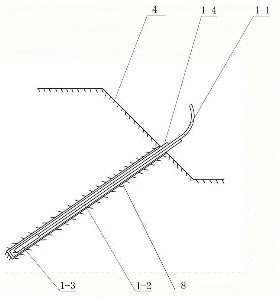
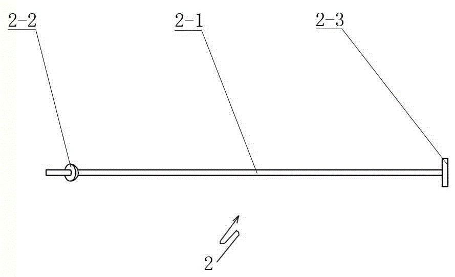
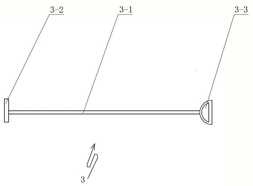
[0031] Such as figure 1 with Image 6 As shown, the settling device of the present invention includes a punching device and a pipe-burying device. The punching device and the buried pipe device are all used in conjunction with the well point downwater pipe 5, and its size is all matched with the size specification of the well point downwater pipe 5. The punching device includes a punching gun 1-2, the rear end of the punching gun 1-2 is connected with a water belt 1-1, the other end of the water belt 1-1 is connected with a high-pressure water pump, and the front end of the punching gun 1-2 is equipped with a punching gun The head 1-3, the front end of the punching gun head 1-3 is tapered, which facilitates the insertion of the punching gun 1-2 in the well hole 8. The outside of the punching gun 1-2 is covered with a casing pipe 1-4. One end of the casing tube 1-4 near the surface of the ba...

Embodiment 2

[0034] Embodiment 2: The settlement method of the well point downwater pipe in the fluid soil layer.

[0035] The settling method of the present invention adopts the settling device described in embodiment 1, and the specific steps of the settling method are:

[0036] (1) if figure 1 , figure 2 , image 3 , Figure 4 with Figure 7 Shown, make matching casing pipe 1-4, punching gun 1-2, push rod 2 and push plate 3 according to the size specification of the well point downcomer 5 to be set. Its dimensional coordination has been briefly explained in Embodiment 1, that is: the inner diameter of the protective tube 1-4 is greater than the outer diameter of the punch head 1-3 gun body, and the outer diameter of the protective tube 1-4 is equal to the pre-designed The inner diameter of a good well hole 8; the diameter of the connecting rod 2-1 is less than the inner diameter of the well point downwater pipe 5; the contact surface of the push rod head 2-2 and the well point dow...


PUM


Abstract

The invention relates to a sinking device and method for a well point drawdown pipe of a liquid soil layer. The sinking device comprises a punching device and a pipe burying device. According to the punching device, a punching gun head is connected to the front end of a punching gun, a water hose used for being connected with a high-pressure water pump is connected to the rear end of the punching gun, and a protective cylindrical pipe is arranged outside the punching gun in a sleeving mode. The pipe burying device comprises a push rod and a push plate. According to the push rod, a handle is connected to one end of a connecting rod, and a push rod end socket is connected to the connecting rod in a sleeving mode. According to the push plate, a push plate head is connected to one end of a linkage rod, a push handle is connected to the other end of the linkage rod, and the push plate head is of a semicircular plate like structure provided with an arc-shaped groove so that filler materials placed in a well pit can be compacted. The sinking device is simple in structure, convenient to operate and practical; the punching device, the push plate and a push gun are used in cooperation, and thus the problem that the wall of the well pit deforms due to retraction of sand and stones is effectively solved. By the adoption of the sinking device and method, the working efficiency of sinking of the well point drawdown pipe can be effectively improved.

Description

technical field [0001] The invention relates to a construction device for a well point downpipe, in particular to a settling device and a settling method for a well point downpipe in a fluid soil layer. Background technique [0002] According to the needs of actual engineering construction and the increasing shortage of construction land, the area selected for construction land is gradually close to the areas along the river, the coast and tidal flats. Such areas are mostly fluid soil layers such as upper sand and lower rocks or tidal mud. When carrying out deep foundation pit construction in such areas, it is first necessary to excavate the foundation pit. During the excavation of the foundation pit, it is necessary to take measures such as precipitation to drain the water in the foundation soil, which can promote the consolidation of the soil and improve the quality of the foundation. At the same time, it can reduce the lateral displacement and settlement of the slope, sta...

Claims


Application Information

Patent Timeline
IPC IPC(8): E02D19/10
Inventor 张宝建
Owner 河北二十冶建设有限公司
Learn More