
High and steep slope concrete sliding form traction control device

A technology of traction control device and traction device, which is applied in water conservancy projects, sea area projects, coastline protection, etc., can solve problems such as bending track and complexity, and achieve the effects of avoiding bending damage, reducing wear, and being safe, practical and reliable

Active Publication Date: 2016-08-24
CHINA GEZHOUBA (GRP) FIRST ENG CO LTD
View PDF6 Cites 0 Cited by
  • Summary
  • Abstract
  • Description
  • Claims
  • Application Information

AI Technical Summary

Problems solved by technology

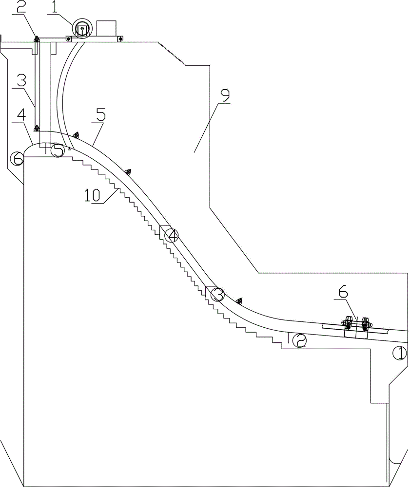
[0003] If the sliding form with rails is adopted, on such a steep overflow surface, how to control the traction mechanism at both ends of the sliding form so that the sliding form can slide up evenly is a very complicated technical and construction problem
In order to ensure the structural size and surface quality of the overflow surface, the gap between the sliding form trolley and the track is set to be small, while the steel of the sliding form body bearing beam is relatively large. If the gap between the two ends of the sliding form is large during the dragging process, There will be accidents such as pulling curved tracks

Method used


Image

  • High and steep slope concrete sliding form traction control device
  • High and steep slope concrete sliding form traction control device
  • High and steep slope concrete sliding form traction control device

Examples


Embodiment Construction

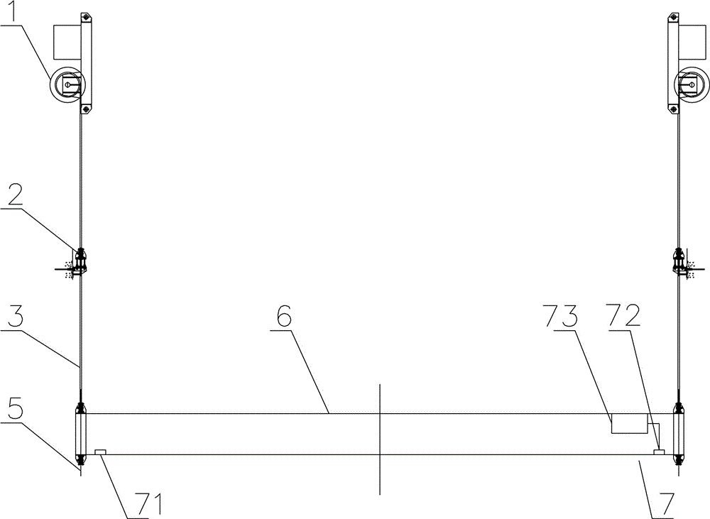
[0029] Such as image 3 Among them, a high and steep slope concrete sliding form traction control device, the two ends of the sliding form body 6 are connected with the traction device, and the sliding form body 6 is provided with a tension detection device 7;

[0030] The structure of the tension detection device 7 is as follows: the laser beam emitting device 71 is located at one end of the sliding form body 6 , the light receiving and detecting device 72 is located at the other end of the sliding form body 6 , and the light receiving and detecting device 72 is connected with the signal processing device 73 . With this structure, when the traction force of the traction device is consistent, the two ends of the sliding form body 6 are flush, and the laser beam emitted by the laser beam emitting device 71 falls on the light receiving and detecting device 72, and the signal processing device 73 can obtain the control signal, and the traction device continues Traction; when the ...


PUM


Abstract

The invention discloses a high-abrupt-slope concrete sliding formwork traction control device. The two ends of a sliding formwork body are connected with traction devices. A tension detection device is arranged on the sliding formwork body. The tension detection device is structurally characterized in that a laser beam transmitting device is located at one end of the sliding formwork body; a light receiving detection device is located at the other end of the sliding formwork body; the light receiving detection device is connected with a signal processing device and is an array type light sensor. According to the high-abrupt-slope concrete sliding formwork traction control device, by means of the structure, consistency of traction force at the two ends of the sliding formwork body can be ensured, the sliding and dragging distance difference of the sliding formwork of each time can be accurately controlled, and parallel dragging of the sliding formwork body is ensured. The structural size of an overflow curved surface and the quality of the surface of shock-resisting, wear-resisting and high-strength concrete are ensured.

Description

technical field [0001] The invention relates to the field of slip-form concrete construction, in particular to a slip-form traction control device for high and steep slope concrete. Background technique [0002] The porous flood gate of a flood gate project of a water conservancy project. The flood discharge sluice chamber of each hole is 15m wide, and the gate pier is 4m thick. The overflow surface of the flood discharge sluice is made of high-strength concrete with anti-scouring and wear resistance, and the curved surface is a combination curve structure of high and steep slopes. The design width of the overflow surface is 15m, the length of the curve is about 90m, and the height difference between the highest point and the lowest point of the curve is about 43m. The overflow surface curve consists of five segments, such as figure 1 As shown in : Section ①-② is an oblique straight line with an included angle of 5 degrees, and the length of the oblique straight line is ab...

Claims


Application Information

Patent Timeline
Patent Type & Authority Patents(China)
IPC IPC(8): E02D15/02E02B7/00
Inventor 黄万林黄金春赵志忠程书祥胡云峰李光誉黎学皓熊建武胡方华
Owner CHINA GEZHOUBA (GRP) FIRST ENG CO LTD
Learn More