Pay-off rack for electric power construction

A technology for electric construction and pay-off rack, applied in the electric field, can solve the problems of short winding length, cable stacking and winding, reducing cable effect, etc.

Inactive Publication Date: 2021-04-30
陈培安
View PDF0 Cites 0 Cited by
  • Summary
  • Abstract
  • Description
  • Claims
  • Application Information

AI Technical Summary

Problems solved by technology

[0002] Cable laying refers to the process of laying and installing cables along the surveyed route to form a cable line. During the laying process of cables, it is necessary to use a pay-off frame to retract and release the cables so that the cables can be laid in an orderly manner. To ensure the transmission quality of the cable line, but in the process of paying off the cable, the thickness of the cable on the pay-off reel gradually decreases wit

Method used


Image

  • Pay-off rack for electric power construction
  • Pay-off rack for electric power construction
  • Pay-off rack for electric power construction

Examples


Embodiment 1

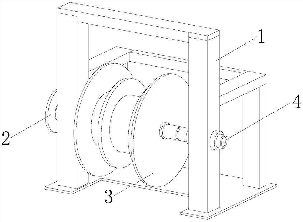
[0024] as attached figure 1 to attach Figure 6 Shown:

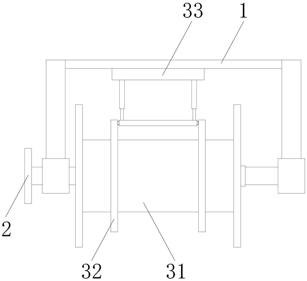
[0025] The present invention is a pay-off frame for electric power construction, its structure includes a support frame 1, a drive plate 2, an unwinder 3, and a connecting shaft 4, and a drive plate 2 is provided outside the left end of the support frame 1, and the drive plate 2 is connected to the release frame. The reel 3 rotates synchronously, the connecting shaft 4 runs through the inside of the unwinder 3, and the right end of the connecting shaft 4 is arranged inside the right end of the support frame 1, and the unwinder 3 includes a pay-off reel 31, a limit disc 32, a traction Device 33, the outer side of the pay-off reel is provided with a limit plate 32, and the connecting shaft 4 runs through the inside of the pay-off reel 31, the traction device 33 is located at the rear side of the pay-off reel 31, and the back of the traction device 33 is connected to the back of the support frame 1 The end phase is welded...

Embodiment 2

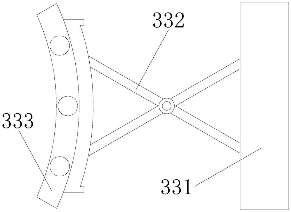
[0033] as attached Figure 7 to attach Figure 8 Shown:

[0034] Wherein, the abutment device 333 includes an abutment plate 33a, a ball 33b, and a snap-fit ​​mechanism 33c, balls 33b are provided inside the front and rear ends of the abutment plate 33a, and the outer surface of the ball 33b is slidably connected with the inner surface of the limit plate 32, so The buckling mechanism 33c is embedded and installed on the left surface of the collision plate 33a. The collision plate 33a has an arc-shaped structure, and the curvature of the collision plate 33a matches the circular curvature of the pay-off reel 31, which is beneficial to the collision plate 33a. The surface of the cable wound on the outside of the coil 31 interferes, thereby applying traction to the cable.

[0035] Wherein, the fastening mechanism 33c includes a separation rod c1, a buckle c2, and a telescopic hose c3. The separation rod c1 is welded to the outer surface of the collision plate 33a, and the buckle...


PUM


Abstract

The invention discloses a pay-off rack for electric power construction. The pay-off rack structurally comprises a supporting frame, a driving disc, an unwinding device and a connecting shaft. The driving disc is arranged on the outer side of the left end of the supporting frame, and the driving disc and the unwinding device rotate synchronously. In the cable pay-off process, the thickness of a cable on a pay-off disc is gradually reduced, at the moment, a sliding block slides on a guide polish rod through the elastic force of a spring, a pushing plate pushes an abutting device in the sliding process, the thickness of the cable on the pay-off disc is gradually reduced, and the abutting device gradually gets close to and abuts against the outer side of the cable on the pay-off disc. It is ensured that the traction force of the whole cable during pay-off is kept consistent, accumulation and winding of later paid-off cables after pay-off are avoided, the cables on the pay-off disc are pushed into buckling strips in order through separation rods, the abutting force with the cables is improved, the cable pay-off speed is prevented from being too high, and the cables can be paid off in order through the buckling strips, so that the orderly laying effect of the cables is improved.

Description

technical field [0001] The invention relates to the field of electric power, and more specifically, relates to a pay-off rack for electric power construction. Background technique [0002] Cable laying refers to the process of laying and installing cables along the surveyed route to form a cable line. During the laying process of cables, it is necessary to use a pay-off frame to retract and release the cables so that the cables can be laid in an orderly manner. To ensure the transmission quality of the cable line, but in the process of paying off the cable, the thickness of the cable on the pay-off reel gradually decreases with the pay-off of the cable, and the speed of the pay-off reel remains unchanged. The traction force on the cable also remains unchanged, and the winding length of the cable and the pay-off reel is shorter at the rear, so that the speed of the cable at the rear is higher than the speed at the front, resulting in the cable at the rear. The paid-off cable...

Claims


Application Information

Patent Timeline
IPC IPC(8): B65H59/38B65H49/30
CPCB65H49/30B65H59/382B65H2701/34
Inventor 刘以南
Owner 陈培安
Why Eureka
Try Eureka