Three-point force tester for cylindrical elastic element
What is Al technical title?
Al technical title is built by PatSnap Al team. It summarizes the technical point description of the patent document.
A technology of elastic components and testing machines, which is applied in the testing of mechanical components, testing of machine/structural components, force/torque/power measuring instruments, etc. It can solve the problems of test point deviation, poor precision, inaccurate data, etc., to achieve The effect of consistent moving distance, accurate elastic force and easy operation
Inactive Publication Date: 2013-11-27
SHANGHAI SAN HUAN SPRING CO LTD
View PDF4 Cites 0 Cited by
Summary
Abstract
Description
Claims
Application Information
AI Technical Summary
This helps you quickly interpret patents by identifying the three key elements:
Problems solved by technology
Method used
Benefits of technology
Problems solved by technology
[0003] 1. The spring force measuring machine uses four chucks. If the layout is slightly uneven, it will cause deviations in the test points and make the collected data inaccurate;
[0004] 2. The four chucks are clamped or loosened by bevel gears, and the precision is poor;
[0005] 3. The existing dynamometer uses readings to display the test results, because the readings are delayed, so the test results cannot be collected continuously, thus affecting the analysis results
Method used
Image
Click on the blue label to locate the original text in one second.
Reading with bidirectional positioning of images and text.
Examples
Embodiment Construction
[0028] The specific features and performances of the present invention are further described by the following embodiments in conjunction with the accompanying drawings.
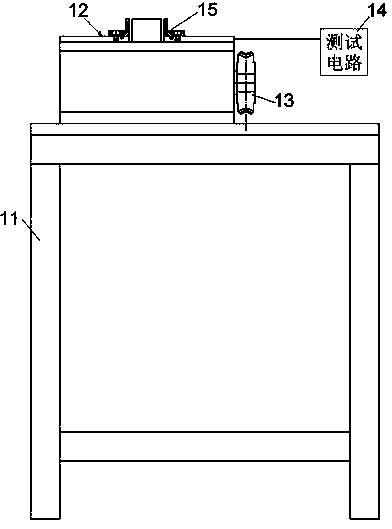
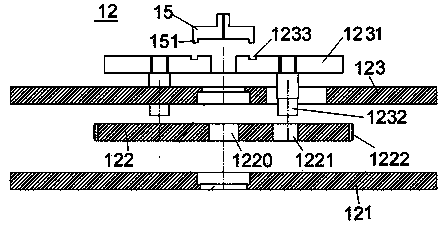
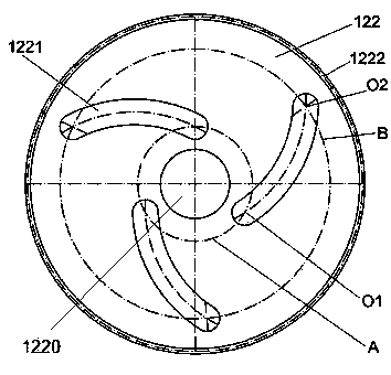
[0029] see figure 1 , figure 2 ,in, figure 1 is a structural schematic diagram of an embodiment of the present invention, figure 2 It is an exploded schematic diagram of an embodiment of the test component in the present invention. A three-point force testing machine for a cylindrical elastic element of the present invention includes a frame 11 , a testing component 12 , a transmission component 13 and a testing circuit 14 . Please refer to figure 2 , the test component 12 includes a chassis 121 , a turntable 122 , and a panel 123 . The panel 123 and the chassis 121 are fixed on the frame at intervals up and down, and the turntable 122 is provided with a shaft hole 1220, which is arranged between the chassis and the panel through the central axis, and the turntable is driven by the transmission part 1...
PUM
Abstract
The invention discloses a three-point force tester for a cylindrical elastic element, which is characterized by comprising a frame, a test part, a transmission part and a test circuit, the test part comprises a base plate, a turntable and a panel, the base plate and the panel are fixed onto the frame, the turntable is arranged between the base plate and the panel through a central shaft and driven to reciprocate by the transmission part, three arc grooves are arranged on the turntable, three sliders are arranged on the panel, a shaft is arranged at the bottom of each slider, a lower section of each shaft is positioned in the corresponding arc groove of the turntable, and the test circuit comprises a pressure sensor, a stroke sensor, a data acquisition module, a data compilation module, a data processing module, a curve output module and a display module, wherein the data acquisition module is used for receiving output signals of the pressure sensor and the stroke sensor, the data compilation module is used for converting analog signals into digital signals, the data processing module is used for recording the position of each datum outputted by the data compilation module on a coordinate and converting the position into a curve trace, the curve output module is used for outputting continuous curves, and the display module is used for displaying curve results. The three-point force tester has the advantages of simplicity and convenience in operation, accuracy in testing and capability of outputting the continuous curves.
Description
technical field [0001] The invention relates to a force measuring machine for an elastic element, in particular to a three-point force testing machine for a cylindrical elastic element. Background technique [0002] In order to test the clamping ability of the elastic element, especially the cylindrical elastic element such as the clip spring, a dynamometric test is generally carried out on the clip spring. Due to its structure, the existing spring force measuring machine has the following problems: [0003] 1. The spring force measuring machine uses four chucks. If the layout is slightly uneven, it will cause deviations in the test points and make the collected data inaccurate; [0004] 2. The four chucks are clamped or loosened by bevel gears, and the precision is poor; [0005] 3. The existing dynamometer uses readings to display the test results, because the readings are delayed, so the test results cannot be collected continuously, thereby affecting the analysis resul...
Claims
Application Information
Patent Timeline
Application Date:The date an application was filed.
Publication Date:The date a patent or application was officially published.
First Publication Date:The earliest publication date of a patent with the same application number.
Issue Date:Publication date of the patent grant document.
PCT Entry Date:The Entry date of PCT National Phase.
Estimated Expiry Date:The statutory expiry date of a patent right according to the Patent Law, and it is the longest term of protection that the patent right can achieve without the termination of the patent right due to other reasons(Term extension factor has been taken into account ).
Invalid Date:Actual expiry date is based on effective date or publication date of legal transaction data of invalid patent.