Numerically-controlled drilling and chamfering machine

A technology of chamfering machine and CNC slide table, which is applied in boring/drilling, drilling/drilling equipment, metal processing machinery parts, etc. Problems such as low operation efficiency, to achieve the effect of saving manpower handling, preventing oil cylinder wall strain, and high production efficiency

Inactive Publication Date: 2015-10-14
湖北佳恒科技股份有限公司
View PDF0 Cites 3 Cited by
  • Summary
  • Abstract
  • Description
  • Claims
  • Application Information

AI Technical Summary

Problems solved by technology

The position and roughness of the oil return holes of the front-end multi-stage sleeve hydraulic cylinders directly affect the overall performance and quality of the hydraulic cylinder. Therefore, the accuracy of the oil hole positions must be required during the processing of the cylinders at all levels. , roughness; there are flashes and burrs in the inner hole of the cylinder after the rocker arm drills the hole, and special personnel must be arranged to clean up the processing defects, which not only prolongs the overall turnaround time but also increases the labor intensity of the manual operation, and the operation efficiency is low.
[0003] At the same time, there are certain difficulties in the quality control of the oil return hole

Method used


Image

  • Numerically-controlled drilling and chamfering machine
  • Numerically-controlled drilling and chamfering machine
  • Numerically-controlled drilling and chamfering machine

Examples


specific Embodiment approach

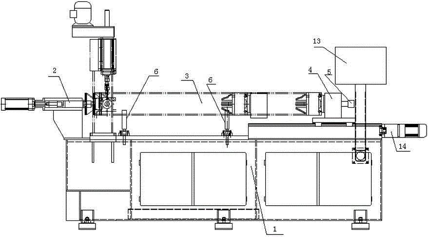
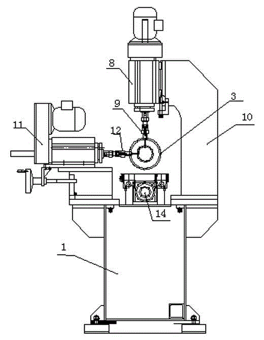
[0019] The present invention as figure 1 , 2 shown.

[0020] The CNC drilling and chamfering machine includes a working platform 1, an electric control system 13 is provided on the side of the working platform 1, a bracket 6 is provided in the middle of the working platform 1, a positioning and tightening device 2 is provided at one end of the working platform 12, and a positioning and tightening device 2 is provided at the other end. Servomotor 5 is provided with indexing plate 7, and indexing plate 7 is provided with tightening device two correspondingly; The working platform 1 outside positioning tightening device one 2 is provided with two drill floors through support arm 10, namely drill floor one 11 And drill floor two 8, two drill floors are provided with drill jacket two 9 and drill floor one 11 respectively.

[0021] Below the servo motor 5 and the index plate 7, a numerical control slide table 14 is arranged.

[0022] The positioning tightening device-2 is a pneum...


PUM


Abstract

The invention provides a numerically-controlled drilling and chamfering machine. An electric control system is arranged on the side edge of a working platform. A support is arranged in the middle of the working platform. A first positioning and tightening device is arranged at one end of the working platform. A dividing plate is arranged at the other end of the working platform through a servo motor. A second tightening device is correspondingly arranged on the dividing plate. Two drill stands are arranged on the portion, located outside the first positioning and tightening device, of the working platform through supporting arms. The two drill stands are provided with drill jackets respectively. A numerically-controlled sliding table is arranged below the servo motor and the dividing plate. The first positioning and tightening device is a pneumatic positioning and tightening device. The two drill stands are perpendicular to each otheraccording to the relative positions. According to the numerically-controlled drilling and chamfering machine, the technical problem that chamfering and deburring of the orifice of an oil hole in the inner wall of a cylinder pipe cannot be achieved is solved, damage of an oil cylinder sealing piece and scratch of the inner wall of the oil cylinder are effectively prevented, and product quality is greatly improved; different requirements for machining of four oil holes, eight oil holes and the like can be met at a time; on the premise that drilling of a cylinder barrel is completed, the machining cycle is shortened, labor intensity is relieved, and working efficiency is improved.

Description

technical field [0001] The invention is a numerically controlled automatic equipment capable of quickly solving the multi-angle, multi-direction, high-precision drilling and chamfering of the internal cylinder barrel of a multi-stage front hydraulic cylinder. Background technique [0002] The front-mounted multi-stage sleeve hydraulic cylinder is one of the core components of the dump truck, and the performance characteristics of each part are directly related to the overall function of the dump truck. The key to restricting the production and development of hydraulic cylinders is reflected in the fine management, especially the effective control of each production link. The preventive and corrective measures in the production process have become the key to winning the market competition. The position and roughness of the oil return holes of the front-end multi-stage sleeve hydraulic cylinders directly affect the overall performance and quality of the hydraulic cylinder. Th...

Claims


Application Information

Patent Timeline
IPC IPC(8): B23B39/24B23Q3/08
CPCB23B39/24B23B39/16B23B41/00B23Q3/08B23Q16/06B23Q2703/04
Inventor 赵伟蔡冉袁春辉李强郭庭均金兰兵
Owner 湖北佳恒科技股份有限公司
Why Eureka
Try Eureka