
Permanent magnet cavity structure robust design method capable of reducing iron loss of built-in permanent magnet motor

A permanent magnet motor and permanent magnet technology, which is applied to the shape/style/structure of the magnetic circuit, the rotating parts of the magnetic circuit, and the manufacture of the stator/rotor body. , to achieve the effect of reducing harmonic components, electromagnetic torque fluctuation and cogging torque, and improving stability

Active Publication Date: 2015-10-07
TIANJIN UNIV
View PDF1 Cites 15 Cited by
  • Summary
  • Abstract
  • Description
  • Claims
  • Application Information

AI Technical Summary

Problems solved by technology

[0005] At present, the methods of optimizing the motor are divided into global optimization design method and local optimization design method. The global optimization design method includes genetic algorithm, simulated annealing method and tabu search and other intelligent optimization algorithms. The global optimization design method can eliminate all uncertain factors. Included in the optimization objective, but the establishment of the specific objective function is very complicated, the cost of calculation is very large, and the calculation time is very long; local optimization design methods include deterministic methods such as compound shape method, simplex method, and mountain climbing method. The linear optimization design method has a good convergence effect for single-objective optimization, but it cannot achieve multi-objective optimization design.

Method used


Image

  • Permanent magnet cavity structure robust design method capable of reducing iron loss of built-in permanent magnet motor
  • Permanent magnet cavity structure robust design method capable of reducing iron loss of built-in permanent magnet motor
  • Permanent magnet cavity structure robust design method capable of reducing iron loss of built-in permanent magnet motor

Examples


Embodiment Construction

[0025] The present invention will be described in further detail below in conjunction with the embodiments and accompanying drawings. Taking a built-in permanent magnet motor as an example, the robustness design of the permanent magnet cavity structure to reduce the iron loss of the built-in permanent magnet motor is carried out. The parameters of the motor are shown in Table 1.

[0026] Table 1 Inner rotor motor parameters

[0027] parameters

the symbol

value

unit

Rated speed

n N

1800

r / min

Rated torque

T N

960

N m

Number of pole pairs

P

4

--

Number of slots

Q

48

--

Rotor air gap radius

R ra

148.2

mm

air gap length

δ

1.8

mm

Radius at stator yoke

R sy

232.5

mm

core length

l

210

mm

permanent magnet residual flux density

B r

1.19

T

[0028] Permanent magnet relative perme...


PUM


Abstract

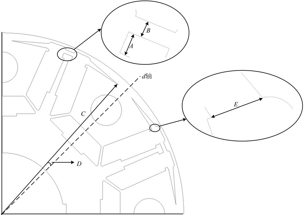
The invention relates to a permanent magnet cavity structure robust design method capable of reducing iron loss of a built-in permanent magnet motor. The method comprises steps: initial permanent magnet cavity structures of the motor are determined, and the built-in permanent magnet motor adopts a single layer of U-type permanent magnet structures; the permanent magnet cavity structures of the motor are improved, triangular permanent magnet cavity expansion structures are added at places, near the surface of a rotor iron core, at two sides of each U-type permanent magnet cavity, and the permanent magnet cavities between adjacent poles are connected; and a Taguchi method is used for optimizing the permanent magnet cavity improved structures. The permanent magnet cavity structures of the built-in permanent magnet motor with the single layer of U-type permanent magnet structures are improved, the improved structure can effectively reduce the harmonic component in an air-gap magnetic field, iron loss of the stator and the rotor of the motor is reduced obviously, the optimized permanent magnet cavity structure enables electromagnetic torque ripple and cogging torque of the motor to be reduced obviously, and smooth operation of the motor is enhanced.

Description

Technical field [0001] The invention belongs to the field of motor robustness design, and in particular relates to the robustness design of a permanent magnet cavity structure for reducing the iron loss of a built-in permanent magnet motor. Background technique [0002] The permanent magnet of the built-in permanent magnet motor is located inside the rotor, and there is a ferromagnetic material between the outer surface of the permanent magnet and the inner circle of the rotor core (for the outer rotor magnetic circuit structure, it is between the inner surface of the permanent magnet and the inner circle of the rotor core). Formed pole shoes, which makes the d, q-axis magnetic circuit asymmetrical, that is, L d ≠ L q , due to the asymmetry of the rotor magnetic circuit structure, the motor generates reluctance torque, which makes the interior permanent magnet motor have higher power density and torque density, and the reluctance torque also helps to improve the overload ca...

Claims


Application Information

Patent Timeline
IPC IPC(8): H02K15/03H02K1/27
Inventor 夏长亮郭丽艳张振史婷娜王慧敏
Owner TIANJIN UNIV
Learn More