
Permanent magnet motor cooling system for railway vehicle

A technology for permanent magnet motors and rail vehicles, which is applied in the direction of cooling/ventilation devices, electrical components, electromechanical devices, etc., and can solve the problems of limited heat dissipation capacity of permanent magnet motors and inability to dissipate heat of permanent magnet motors

Active Publication Date: 2018-11-23
CRRC TANGSHAN CO LTD
View PDF5 Cites 6 Cited by
  • Summary
  • Abstract
  • Description
  • Claims
  • Application Information

AI Technical Summary

Problems solved by technology

[0005] An embodiment of the present invention provides a permanent magnet motor cooling system for rail vehicles to improve the problem that the self-ventilated cooling mode of permanent magnet motors has limited heat dissipation capacity and cannot effectively dissipate heat for larger power permanent magnet motors for rail vehicles

Method used


Image

  • Permanent magnet motor cooling system for railway vehicle
  • Permanent magnet motor cooling system for railway vehicle
  • Permanent magnet motor cooling system for railway vehicle

Examples


Embodiment Construction

[0046] In order to make the purpose, technical solutions and advantages of the embodiments of the present invention clearer, the technical solutions in the embodiments of the present invention will be clearly and completely described below in conjunction with the drawings in the embodiments of the present invention. Obviously, the described embodiments It is a part of embodiments of the present invention, but not all embodiments. Based on the embodiments of the present invention, those skilled in the art have obtained it without making creative efforts.

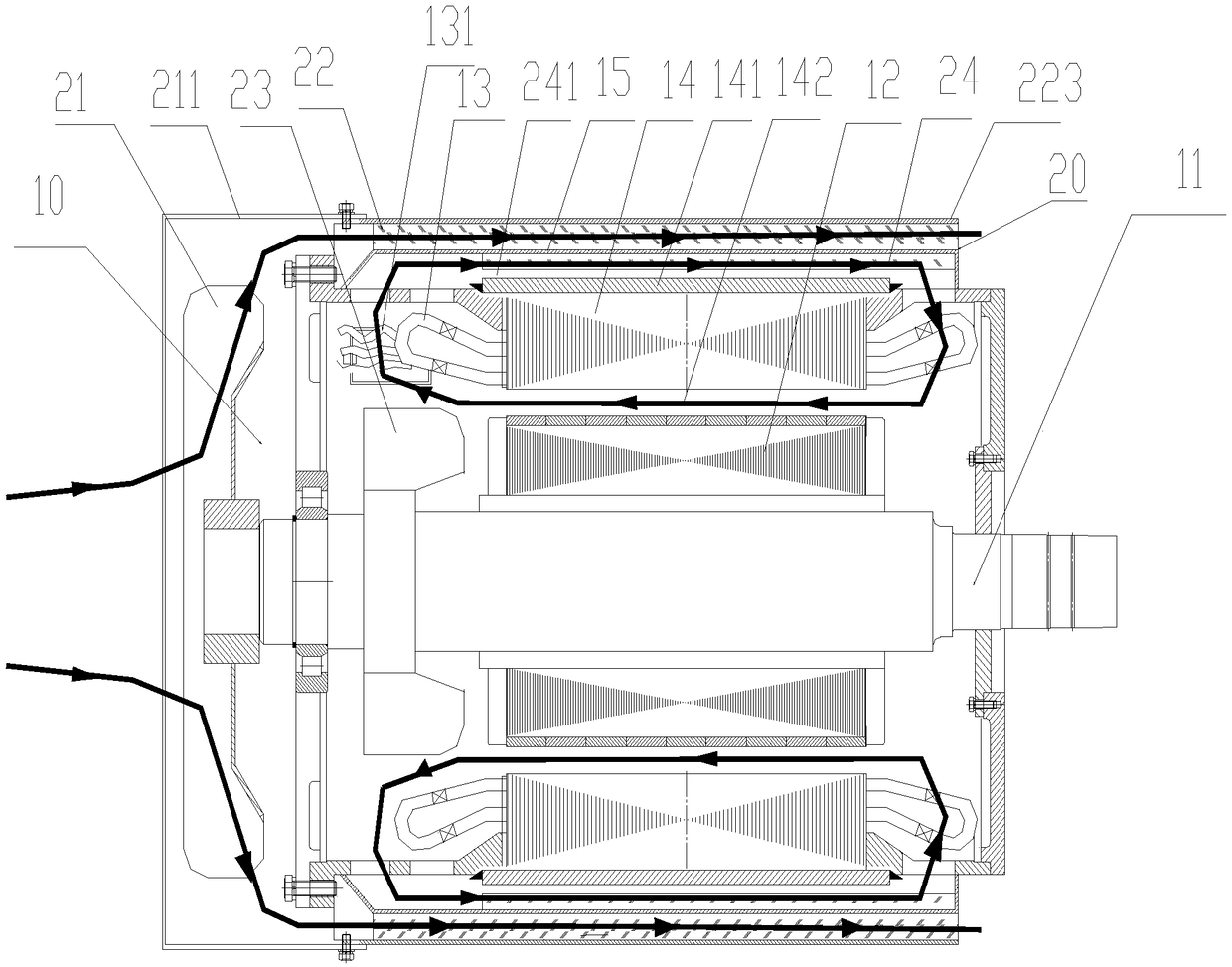
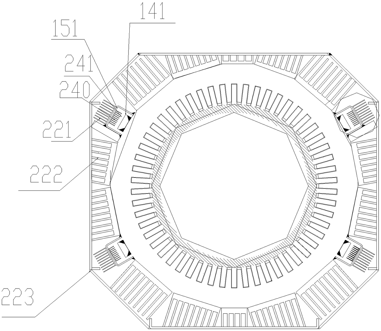
[0047] figure 1 A cross-sectional view of a permanent magnet motor cooling system for a rail vehicle provided by an embodiment of the present invention. like figure 1 As shown, the system includes a permanent magnet motor 1 for rail vehicles and a cooling device 20. The permanent magnet motor 1 for rail vehicles includes a motor body 10, and the motor body 10 includes a rotor shaft 11 and is arranged outside the rotor shaft...


PUM


Abstract

An embodiment of the invention provides a permanent magnet motor cooling system for a railway vehicle. The system comprises a permanent magnet motor and a cooling device, wherein the permanent magnetmotor comprises a motor body; the motor body comprises a rotor rotating shaft, a rotor, a stator winding, a stator and a shell; the cooling device comprises an outer air channel cooling fan, an outerwind path heat dissipation part, an inner air channel cooling fan and an inner wind path heat dissipation part; the inner air channel cooling fan is arranged at one end of the rotor rotating shaft inthe motor body; a heat conduction strip is arranged on the outer side wall of the stator; the inner wind path heat dissipation part is arranged on the outer side of the heat conduction strip in a sleeved mode; an inner wind path gap is formed between the inner wind path heat dissipation part and the outer side wall of the heat conduction strip; a stator rotor gap exists between the inner side wallof the stator and the rotor; the inner wind path gap is in clearance connection with the stator rotor to form an inner wind path; the outer air channel cooling fan is arranged on the rotor rotating shaft and is arranged outside the motor body; and the outer wind path heat dissipation part is arranged on the outer side of the shell. According to the embodiment, the permanent magnet motor for the railway vehicle can be effectively cooled.

Description

technical field [0001] The invention relates to the technical field of permanent magnet motors, in particular to a cooling system for permanent magnet motors used in rail vehicles. Background technique [0002] The motor plays a very important role in the vehicle. At present, more and more motors use permanent magnet motors. Due to the special requirements of permanent magnets, the permanent magnet motors need to be designed as a closed structure. Due to the limited space on the vehicle, the motor Cooling requirements are relatively high. [0003] The temperature rise of the permanent magnet motor is mainly divided into the iron loss caused by the stator and the copper loss caused by the stator winding. In the prior art, the common cooling method adopted by permanent magnet motors for rail vehicles is mainly the self-ventilation cooling method, and the self-ventilation cooling method uses air as the cooling medium. The specific implementation process is: installing heat sin...

Claims


Application Information

Patent Timeline
IPC IPC(8): H02K9/06H02K9/08H02K5/18
CPCH02K5/18H02K9/06H02K9/08
Inventor 康莉莉姜东杰孙开意陈瑞涵杨博于红
Owner CRRC TANGSHAN CO LTD
Learn More