Pulse detection sensing system based on loss suppression

A technology of pulse detection and loss suppression, applied in the field of electronic sensors, can solve problems such as interference, and achieve the effect of reducing loss, reducing loss and being cheap.

Inactive Publication Date: 2015-10-07
CHENGDU JIESHENG TECH CO LTD
View PDF0 Cites 1 Cited by
  • Summary
  • Abstract
  • Description
  • Claims
  • Application Information

AI Technical Summary

Problems solved by technology

[0004] The purpose of the present invention is to overcome the defect that current sensors are easily disturbed when detecting pulse errors, and to provide a stable pulse detection sensor system based on loss suppression

Method used


Image

  • Pulse detection sensing system based on loss suppression
  • Pulse detection sensing system based on loss suppression

Examples


Embodiment

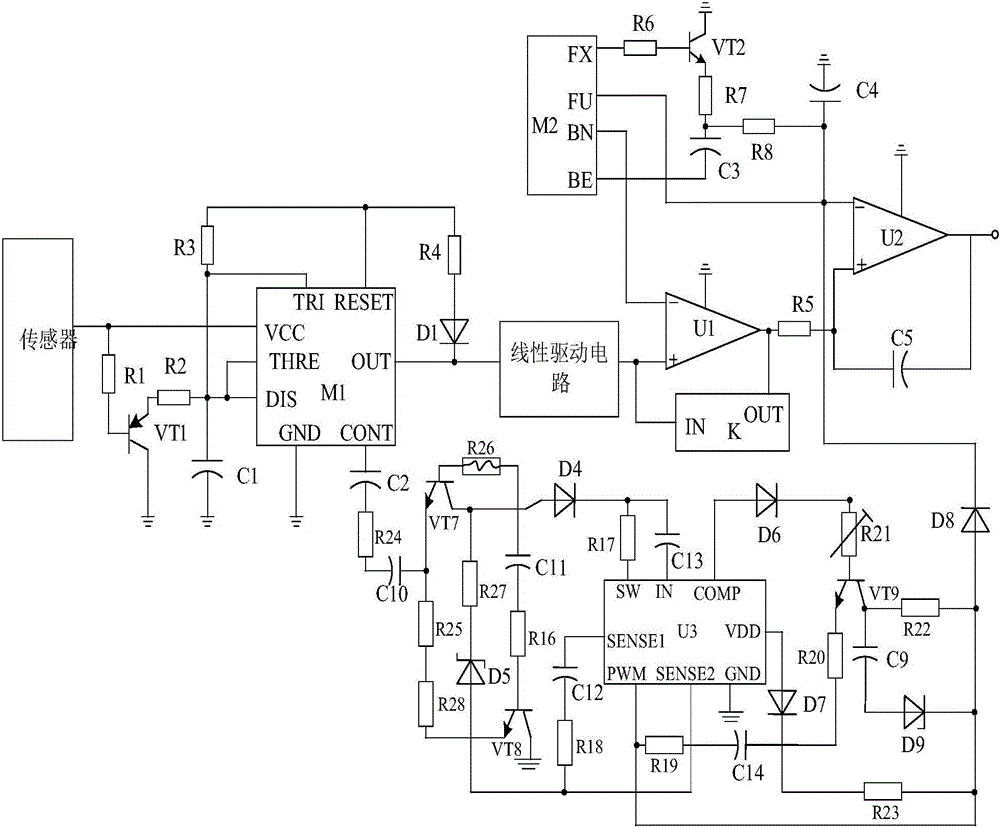
[0019] Such as figure 1 As shown, the present invention consists of a sensor, a main control chip K, a deviation correction circuit connected with the main control chip K, a pulse detection circuit connected with the sensor, a linear drive circuit is arranged between the pulse detection circuit and the deviation correction circuit, and A loss suppression circuit is also arranged between the pulse detection circuit and the deviation correction circuit.

[0020] The loss suppression circuit is composed of suppression chip U3, transistor VT7, transistor VT8, transistor VT9, resistor R16, resistor R17, resistor R18, resistor R19, resistor R20, resistor R21, resistor R22, resistor R23, resistor R24, resistor R25, Resistor R26, resistor R27, resistor R28, diode D4, diode D5, diode D6, diode D7, diode D8, diode D9, polar capacitor C9, polar capacitor C10, polar capacitor C11, polar capacitor C12, polar capacitor C13, and polar capacitor C14.

[0021] When connected, the positive po...


PUM


Abstract

The invention discloses a pulse detection sensor based on linear driving. The pulse detection sensor based on linear driving is mainly composed of a sensor body, a main control chip K, a rectifying circuit connected with the main control chip K, and a pulse detection circuit connected with the sensor body. The pulse detection sensor based on linear driving is characterized in that a linear driving circuit is arranged between the pulse detection circuit and the rectifying circuit and is composed of a driving chip U, a triode VT3, a triode VT4, a triode VT5, a triode VT6, a polar capacitor C6, a resistor R10 and the like, the positive electrode of the polar capacitor C6 is connected with the pulse detection circuit, the negative electrode of the polar capacitor C6 passes through a resistor R9 and then is connected with an IN1 pin of the driving chip U, one end of the resistor R10 is connected with the collector electrode of the triode VT6, and the other end of the resistor R10 passes through a resistor R11 and then is connected with the base electrode of the triode VT3. According to the pulse detection sensor based on linear driving, due to the fact that the linear driving circuit is arranged, it can be guaranteed that the sensor is prevented from being disturbed when used for detecting pulse error signals.

Description

technical field [0001] The invention relates to an electronic sensor, in particular to a pulse detection sensor system based on loss suppression. Background technique [0002] In order to obtain information from the outside world, people must rely on sensory organs. However, relying on people's own sensory organs alone is far from enough for their functions in the study of natural phenomena and laws and production activities. To accommodate this situation, sensors are needed. Therefore, it can be said that the sensor is an extension of human facial features, also known as electrical facial features. [0003] With the advent of the new technological revolution, the world has entered the information age. In the process of using information, the first thing to solve is to obtain accurate and reliable information, and sensors are the main ways and means to obtain information in the natural and production fields. In modern industrial production, especially in the automated pr...

Claims


Application Information

Patent Timeline
Patent Type & Authority Applications(China)
IPC IPC(8): G01D3/028
Inventor 雷明方
Owner CHENGDU JIESHENG TECH CO LTD
Why Eureka
Try Eureka