Eureka AIR delivers breakthrough ideas for toughest innovation challenges, trusted by R&D personnel around the world.

Sign capable of realizing active light emission and intelligent repair as well as control method and applications of sign

An intelligent repair and active light-emitting technology, applied in the field of signs, can solve the problems of incomplete display of signs, symbols or text, poor weather resistance, and difficult repair, etc., and achieve the effects of improving visibility, strong weather resistance, and wide application range

Inactive Publication Date: 2015-09-30
王晓光
View PDF8 Cites 1 Cited by
  • Summary
  • Abstract
  • Description
  • Claims
  • Application Information

AI Technical Summary

Problems solved by technology

However, the existing LED active light-emitting signs also have many shortcomings in the application process. First, LED lamp beads have problems of light decay and dead spots, poor weather resistance, and dead spots of lamp beads will cause incomplete display of signs, symbols or text. And it is not easy to repair, resulting in the obstruction of traffic information transmission
The second is that the LED light-emitting sign circuit part is as prone to failure as all other electrical equipment, resulting in short circuit or open circuit of the equipment, especially in remote roads such as rural areas. Once the above situations occur, emergency maintenance is difficult to do, which will inevitably affect traffic signs usage of

Method used


Image

  • Sign capable of realizing active light emission and intelligent repair as well as control method and applications of sign
  • Sign capable of realizing active light emission and intelligent repair as well as control method and applications of sign
  • Sign capable of realizing active light emission and intelligent repair as well as control method and applications of sign

Examples


Embodiment Construction

[0028] The present invention will be further described in detail below by way of examples.

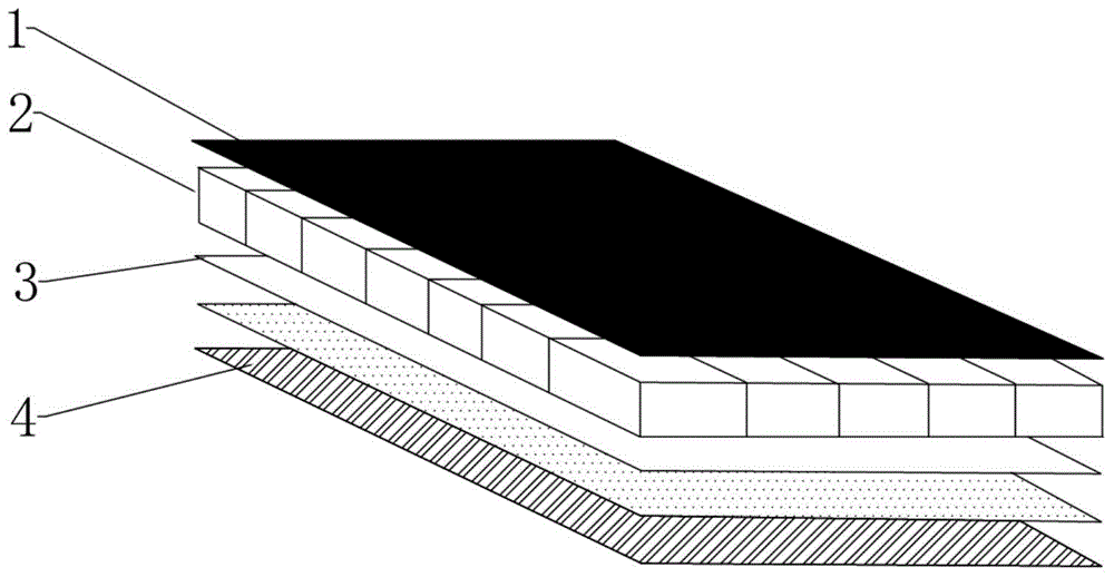
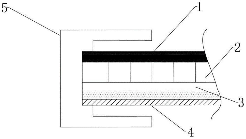
[0029] Such as Figure 1~5 As shown, a signboard capable of active luminescence and intelligent restoration includes a signboard body, an intelligent diagnosis system and a self-response sensing circuit. plate 4; the prism reflective layer 1 is placed on the light-emitting layer 2, and the reflective layer 3 is located between the light-emitting layer 2 and the back plate 4; the light-emitting layer 2 is an independent light-emitting unit integrated by an LED light-emitting diode and a PMMA plate, so that the LED The point light source of the light emitting diode becomes a surface light source due to the principle of optical refraction, that is, the LED-PMMA light emitting unit. As a preferred solution, the intelligent diagnosis system and the self-response sensing circuit are located between the back plate 4 and the reflective layer 3 . In order to ensure good mechanical properties ...


PUM


Abstract

The invention provides a sign capable of realizing active light emission and intelligent repair as well as a control method and applications of the sign. The sign comprises a sign body, an intelligent diagnostic system and a self-responding sensing circuit, wherein the sign body comprises a prism reflection layer, a light emitting layer, a light reflecting layer and a backboard; the prism reflection layer is arranged on the light emitting layer, and the light reflecting layer is located between the light emitting layer and the backboard; the light emitting layer is an independent light emitting unit formed by integrating LEDs and a PMMA (polymethyl methacrylate) board; an adjusting circuit and a backup circuit are arranged on the self-responding sensing circuit; each LED is divided into a light emitting module and a backup module which are independent of each other; the intelligent diagnostic system detects and judges working states of all the light emitting modules; the self-responding sensing circuit controls the light emitting modules and the backup modules. The sign can monitor circuit states in real time, has the advantages of high vision recognition ratio, high weather resistance, low energy consumption, capability of realizing failure self-detection and intelligent repair and the like, and is excellent in mechanical property and wide in application range.

Description

technical field [0001] The invention relates to a signboard, in particular to a signboard capable of active luminescence and intelligent restoration, a control method thereof and the application of the signboard on road traffic signs and motor vehicle license plates. Background technique [0002] Road traffic signs are traffic management facilities that use graphic symbols, colors and text to convey specific information to traffic participants. The most primitive road traffic signs are usually made of pigments, paints, wood, and iron sheets, which can only be recognized at close range under simple and good sight conditions. [0003] At the beginning of the 20th century, Dr. Dong Qifang invented and developed the reflective film technology, and applied it to the road traffic sign manufacturing industry. Its working principle is that when the "high beam" of the vehicle shines on the reflective film material on the surface of the traffic sign, a retroreflective light source is...

Claims


Application Information

Patent Timeline
IPC IPC(8): G09F13/22E01F9/00G09F7/00
Inventor 王晓光
Owner 王晓光
Why Eureka
Eureka Blog
Learn More