Information protection device and protection method
An information protection and protection device technology, applied in the protection of internal/peripheral computer components, etc., can solve the problems of great security and hidden dangers of devices
- Summary
- Abstract
- Description
- Claims
- Application Information
AI Technical Summary
Problems solved by technology
Method used
Image
Examples
Embodiment 1
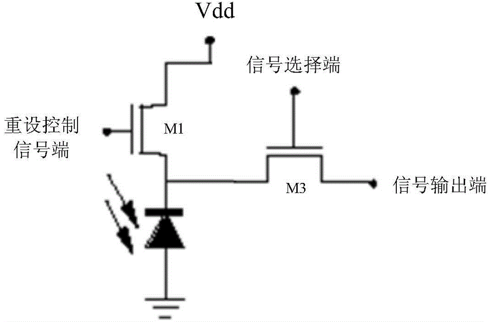
[0036] In the present invention, the information protection device includes a control circuit and a photodiode, wherein the control circuit and the photodiode are connected in series, and control the conduction of the photodiode to realize the potential signal reset to prevent leakage of information.
[0037] Such as Figure 1a As shown, the control circuit at least includes a reset transistor M1 and an output transistor M3, wherein the drain of the reset transistor M1 is connected to the power supply voltage, and the gate of the reset transistor M1 is connected to the reset control signal connected, the source of the reset transistor M1 is connected to the drain of the output transistor M3, and the source of the output transistor M3 is connected to the signal output terminal;
[0038] Wherein, the cathode of the photodiode is connected to the source of the reset transistor M1, and the anode of the photodiode is grounded.
[0039] Preferably, the gate of the output transisto...
Embodiment 2
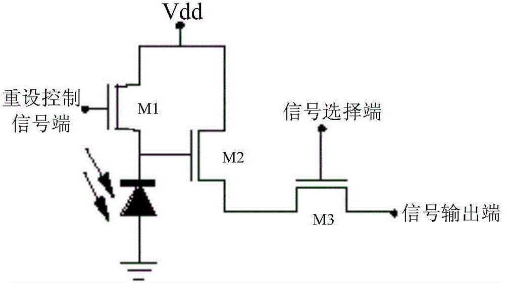
[0049] The control circuit is not limited to the above two transistors, in order to better control the photodiode, the control circuit may further include a plurality of auxiliary transistors, the number of the auxiliary transistors is not limited to a certain A numerical range, for example, can be 1, or more, and can be set as required.
[0050] In this example, if Figure 1b As shown, the control circuit further includes a second transistor M2 disposed between the reset transistor M1 and the output transistor M3, the gate of the second transistor M2 is connected to the source of the reset transistor M1 , the source of the second transistor M2 is connected to the power supply voltage, and the drain of the second transistor M2 is connected to the drain of the output transistor M3.
[0051] Wherein, the reset transistor M1 , the output transistor M3 , the arrangement manner of the photodiode, and the protection method of the protection device can refer to Embodiment 1, and wil...
Embodiment 3
[0053] The protection device of the present invention can be applied not only in the EEPROM process, but also in other commonly used storage devices in the field, which will not be repeated here.
[0054] An embodiment of the present invention provides an electronic device, including an information storage device and the information protection device according to any one of claims 1-6.
[0055] Wherein, the information storage device includes EEPROM, and the electronic device includes a bank card and a financial card.
PUM
 Abstract
Description
Claims
Application Information
 - R&D
- Intellectual Property
- Life Sciences
- Materials
- Tech Scout
- Unparalleled Data Quality
- Higher Quality Content
- 60% Fewer Hallucinations
Browse by: Latest US Patents, China's latest patents, Technical Efficacy Thesaurus, Application Domain, Technology Topic, Popular Technical Reports.
© 2025 PatSnap. All rights reserved.Legal|Privacy policy|Modern Slavery Act Transparency Statement|Sitemap|About US| Contact US: help@patsnap.com


