
Color visual effect device and color visual effect generation method

A color vision, primary color technology, applied in nonlinear optics, instruments, optics, etc., to reduce production costs and complexity of production processes, improve speed and resolution, and improve yields

Inactive Publication Date: 2015-09-23
衷健 +1
View PDF5 Cites 7 Cited by
  • Summary
  • Abstract
  • Description
  • Claims
  • Application Information

AI Technical Summary

Problems solved by technology

[0006] The technical problem to be solved by the present invention is to simplify the structure of the color display screen, improve the display speed and resolution, reduce the complexity and cost of production and process, improve the yield, and avoid visual interference such as vertical lines, twill lines, and water lines. Effect color visual effect device, and a color visual effect generation method using the color visual effect device is provided

Method used


Image

  • Color visual effect device and color visual effect generation method
  • Color visual effect device and color visual effect generation method
  • Color visual effect device and color visual effect generation method

Examples


Embodiment 1

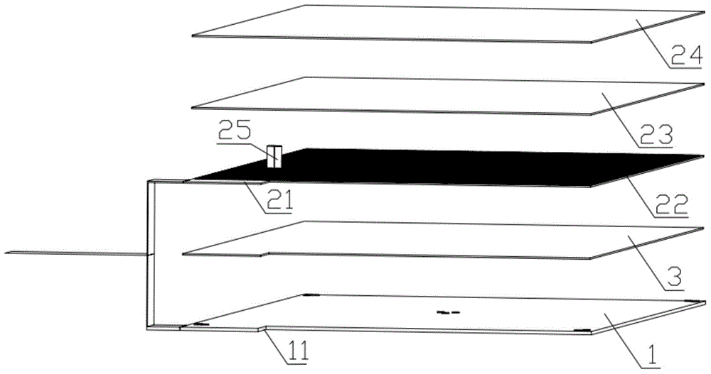
[0027] Such as figure 1 As shown, this example provides a color visual effect device, including: a multi-primary light source 1, a light source driving circuit 11, a display panel 2 and a panel driving circuit 21, the light source driving circuit 11 is connected to the multi-primary light source 1, and the The panel drive circuit 21 is connected to the display panel 2, the display panel 2 is arranged above the multi-primary light source 1, and the light source drive circuit 11 and the panel drive circuit 21 are connected together; wherein, each of the multi-primary light source 1 Each of the primary colors occupies a time slot, and all the primary colors of the multi-primary light source 1 are displayed through the same pixel point of the display panel 2, and all the primary colors of the multi-primary light source 1 are arranged in time order and transmitted by the multi-primary light source 1 to the display Panel 2 to composite the colors.

[0028] The multi-primary color l...

Embodiment 2

[0035] Such as Figure 4 As shown, this example also provides a method for generating a color visual effect, which adopts the color visual effect device as described in Embodiment 1, and includes the following steps:

[0036] Step S1, various primary colors of the multi-primary light source 1 alternately provide light sources or backlights according to a certain time sequence;

[0037] Step S2, the light source driving circuit 11 extracts the working time slots of various primary colors of the multi-primary light source 1 in step S1;

[0038] Step S3 , the panel driving circuit 21 controls the pixels of the display panel 2 to follow and adjust the grayscale component changes according to the working time slots of various primary colors in step S2 , so that all primary colors can complete the display of grayscale components in time sequence.


PUM


Abstract

The invention provides a color visual effect device and a color visual effect generation method. The color visual effect device comprises a multi-primary-color light source, a light source drive circuit, a display panel and a panel drive circuit. The light source drive circuit is connected with the multi-primary-color light source, the panel drive circuit is connected with the display panel, the display panel is arranged above the multi-primary-color light source, and the light source drive circuit and the panel drive circuit are connected together. Each primary color of the multi-primary-color light source occupies one time slot, all the primary colors of the multi-primary-color light source are displayed through the same pixel point of the display panel, and all the primary colors of the multi-primary-color light source are arranged in the time sequence and transmitted to the display panel through the multi-primary-color light source for color synthesis. The structure of a traditional color liquid crystal display screen is changed, a color film filter is omitted, a light source is changed into the multi-primary-color light source, color synthesis is achieved in a time division mode, the display resolution ratio is greatly increased, and the complexity and the cost of production and the process are reduced.

Description

technical field [0001] The invention relates to a visual device, in particular to a color visual effect device, and to a color visual effect generation method using the color visual effect device. Background technique [0002] The existing LCD color display is mainly based on TFT-LCD (Thin Film Transistor-LCD) technology, each pixel is composed of three sub-pixels, and these three sub-pixels are respectively covered by red, green and blue color filter films; if A TFT display with a resolution of 1280x1024 requires at least 1280x3x1024 sub-pixels and transistors, and the smaller the pixel, the greater the possible resolution of the display. [0003] However, due to the limitations of the physical characteristics of transistors, the size of each pixel of a TFT is basically 0.0117 inches (0.297mm). For a 15-inch display, the resolution is generally only 1024x768. To make a display with a higher resolution, you need to use Larger screen; if it is made into a glasses-style displ...

Claims


Application Information

Patent Timeline
IPC IPC(8): G02F1/13357G09G3/36G09G3/34
CPCG02F1/133621G09G3/342G09G3/36
Inventor 衷健陈纪军
Owner 衷健
Learn More