
Shielded twisted pair conductors using conductive ink

A twisted pair, conductor technology, used in shielding materials, instruments for radiological diagnosis, catheters, etc.

Inactive Publication Date: 2017-08-25
ST JUDE MEDICAL INT HLDG SARL
View PDF6 Cites 0 Cited by
  • Summary
  • Abstract
  • Description
  • Claims
  • Application Information

AI Technical Summary

Problems solved by technology

The third floor is above the second floor

Method used


Image

  • Shielded twisted pair conductors using conductive ink
  • Shielded twisted pair conductors using conductive ink
  • Shielded twisted pair conductors using conductive ink

Examples


Embodiment Construction

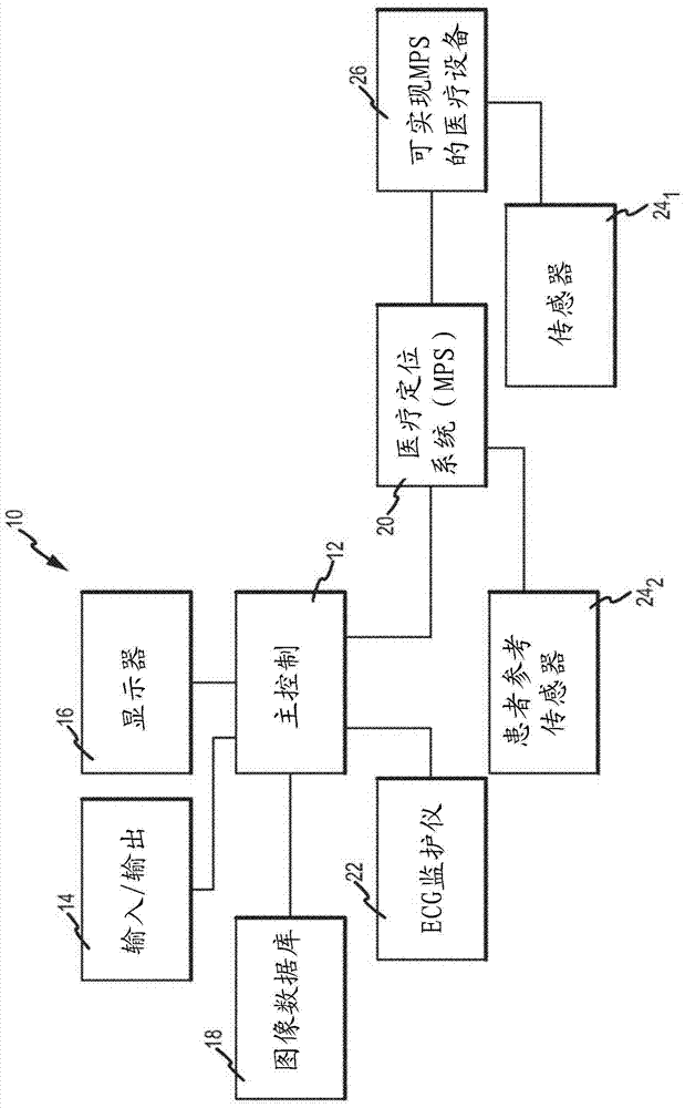
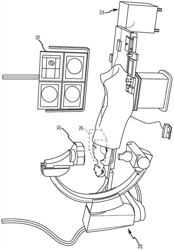
[0024] Various embodiments are described herein with respect to various devices, systems and / or methods. Numerous specific details are set forth to provide a thorough understanding of the overall structure, function, manufacture and use of the embodiments described in the specification and illustrated in the drawings. However, it will be understood by those skilled in the art that these embodiments may be practiced without these specific details. In other instances, well-known operations, components and elements have not been described in detail so as not to obscure the embodiments described in the specification. Those skilled in the art can understand that the embodiments described and illustrated herein are non-limiting examples, and therefore it can be understood that the specific structural and functional details disclosed herein are representative and do not limit the scope of the embodiments. The scope is limited only by the appended claims.

[0025] Reference througho...


PUM


Abstract

A device for transmitting electrical signals is disclosed. The device includes a base and twisted-pair conductors on the base. The twisted pair conductors include a first layer comprising a conductive material, a second layer comprising a non-conductive material, and a third layer comprising a conductive material. The first layer has a plurality of sections separated by a plurality of gaps. The second layer is located within the gap and electrically insulates portions of the segment located within the gap. The third layer is located on the second layer. The third layer is configured to electrically connect one end of one segment to one end of the other segment. The twisted-pair conductor formed by the three-dimensional structure comprises two electrically isolated conductors twisted to each other.

Description

[0001] Cross References to Related Applications [0002] This application claims priority to US Patent Application No. 13 / 753,117, filed January 29, 2013, which is hereby incorporated by reference as if fully set forth herein. technical field [0003] The present invention relates generally to shaped electrical conductors having multiple layers of conductive and non-conductive materials. Background technique [0004] Various procedures in or on a patient's body (e.g., in the circulatory system, gastrointestinal tract, cerebral vessels, bronchial tree, etc.) can be performed or aided by inserting a medical device into a body cavity and then navigating a diagnostic or therapeutic medical device to a target anatomical site. diagnostic and therapeutic procedures. The object can be operated using electrical power on the distal portion of the medical device to aid in the diagnostic, therapeutic and navigational functions of the medical device. The proximal portion of the medica...

Claims


Application Information

Patent Timeline
Patent Type & Authority Patents(China)
IPC IPC(8): A61B5/06H05K3/46A61B5/0402H05K1/02A61B6/12
CPCA61B5/6847A61B5/6851A61B5/6852A61B6/12A61B5/062H05K3/4685A61B2562/0223A61B2562/182A61B2562/222H05K2201/0715H05K2201/097A61B6/487B33Y80/00A61B2562/227A61B5/318H05K9/0073H05K1/0245A61B5/287A61B5/068A61B2562/125H05K2203/0548H05K2203/30
Inventor L·索比
Owner ST JUDE MEDICAL INT HLDG SARL
Learn More