
Device and method for measuring micropore diffraction wavefront quality

A diffractive wavefront and measurement device technology, applied in the field of optical measurement, can solve problems such as difficult calibration, difficult accurate measurement of detectors, difficult removal, etc.

Inactive Publication Date: 2015-09-16
ACAD OF OPTO ELECTRONICS CHINESE ACAD OF SCI
View PDF8 Cites 12 Cited by
  • Summary
  • Abstract
  • Description
  • Claims
  • Application Information

AI Technical Summary

Problems solved by technology

[0005] The article "Extreme-ultraviolet phase-shifting point-diffraction interferometer a wave-front metrology tool with sub-angstrom reference-wave accuracy" (Appl Opt, 1999, 38(35): 7252-7263) describes in detail the calibration of the above-mentioned systematic error method, the calibration of the former is relatively easy, while the calibration of the latter is difficult due to the inclination of the detector, which is difficult to measure accurately
[0006] The article "Point Diffraction Interferometer System Error Calibration" (Acta Optics Sinica, 2013, 33(7): 0712003) adopts the Michelson interferometer structure, and realizes the independent control of the two micro-hole illumination beams by a beam splitter and a plane mirror, avoiding the grating Introduce errors, but there are still problems of coma introduced by the distance between the two holes and astigmatism introduced by the tilt of the detector, and the latter is difficult to remove

Method used


Image

  • Device and method for measuring micropore diffraction wavefront quality
  • Device and method for measuring micropore diffraction wavefront quality
  • Device and method for measuring micropore diffraction wavefront quality

Examples


Embodiment Construction

[0059] In order to further explain the technical means and effects of the present invention to achieve the intended purpose of the invention, below in conjunction with the accompanying drawings and preferred embodiments, a detailed description of the device and method for measuring the quality of a microhole diffraction wavefront proposed according to the present invention Embodiments, structures, methods, steps, features and effects thereof are described in detail below.

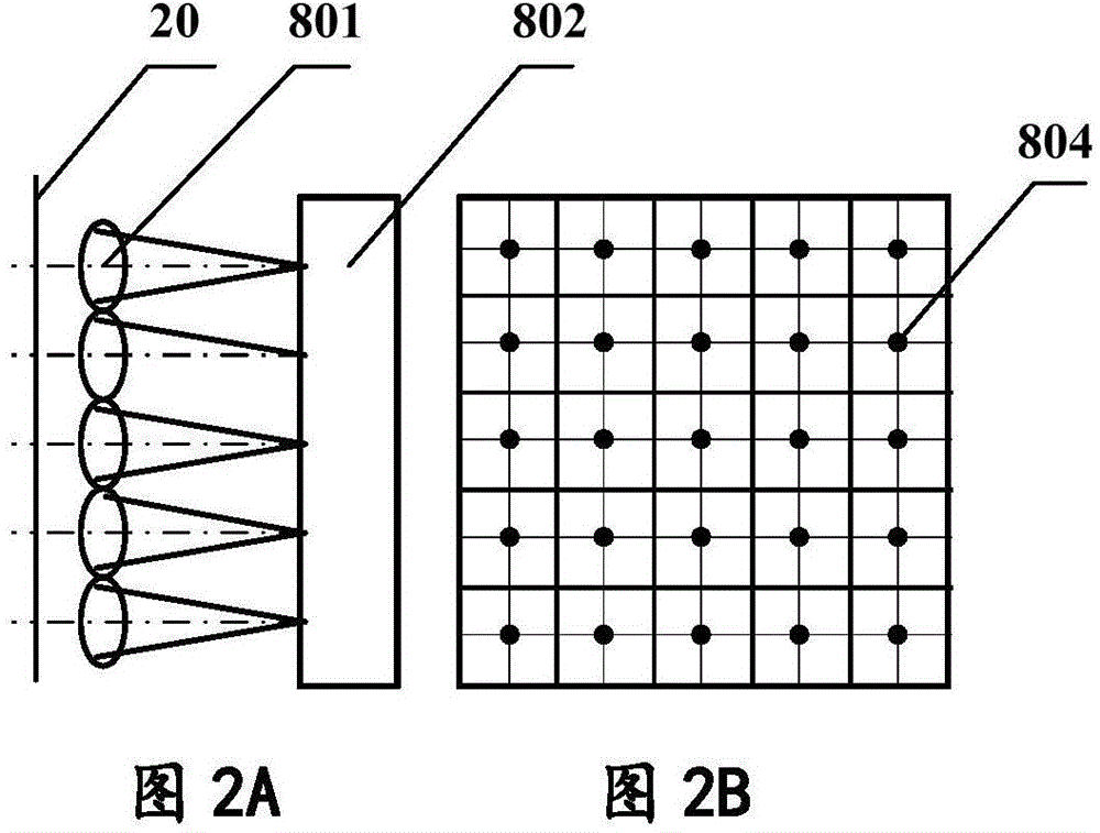
[0060] see figure 1 , Figure 2A and Figure 2B as shown, figure 1 It is a schematic diagram of the principle of high-precision calibration of the Shack-Hartmann wavefront sensor. Figure 2A and Figure 2B It is a schematic diagram of the reference spot array formed when the Shack-Hartmann wavefront sensor is calibrated with high precision. The high-precision plane wave generator 10 and the Shack-Hartmann wavefront sensor 80 form a system error calibration unit. The high-precision plane wave generator ...


PUM


Abstract

The invention relates to a device and a method for measuring the micropore diffraction wavefront quality. According to the invention, measurement is carried out on the micropore diffraction wavefront quality by adopting a Shack-Hartmann wavefront sensor method. High-precision calibration for a Shack-Hartmann wavefront sensor is realized through a high-precision planar reference wavefront, then accurate measurement for the micropore diffraction wavefront shape is carried out according to a calibration result of a high-precision system error, the deviation of the micropore diffraction wavefront can be acquired by comparing the micropore diffraction wavefront shape with an optimal reference sphere, measurement for the micropore diffraction wavefront quality can be realized by only directly adding a focusing objective lens and a micropore on the basis of a calibration device, the operation is simple and convenient, the introduced system error is small, and high-precision calibration for the system error is implemented easily. Spherical aberration introduced by a micropore board can be compensated through the focusing lens, and quick high-precision measurement for the diffraction wavefront quality with different pore sizes can be realized through adjusting the distance between the Shack-Hartmann wavefront sensor and the micropore.

Description

technical field [0001] The invention belongs to the technical field of optical measurement, and in particular relates to a measuring device and method for the quality of microhole diffraction wavefronts for high-precision measurement of wavefronts. Background technique [0002] With the development of semiconductor, aerospace and other technologies, the demand and application of high-precision optical components are becoming more and more extensive. Optical components with nanometer / subnanometer precision play an extremely important role in research fields such as lithography projection objectives, X-ray microscopes, and Michelson interferometers for gravitational wave detection. Therefore, the development of ultra-high-precision surface shape detection technology is an important guarantee for the successful application of high-precision optical components in these fields. [0003] Common commercial Fizeau interferometers and Tieman-Green interferometers have low detection ...

Claims


Application Information

Patent Timeline
Patent Type & Authority Applications(China)
IPC IPC(8): G01J1/00G01J9/00
Inventor 卢增雄梅东滨齐月静孟庆宾刘广义齐威苏佳妮周翊王宇
Owner ACAD OF OPTO ELECTRONICS CHINESE ACAD OF SCI
Learn More